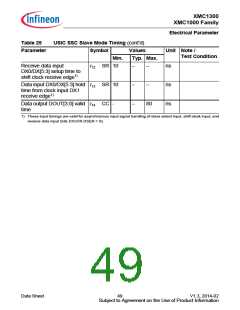
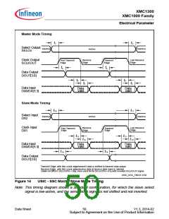
XMC1300
XMC1000 Family
Electrical Parameter
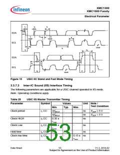
t1
t2
t4
70%
30%
SDA
SCL
t1
t3
t2
t6
9th
clock
t7
t5
t10
S
SDA
SCL
t8
t7
t9
9th
clock
Sr
P
S
Figure 15
USIC IIC Stand and Fast Mode Timing
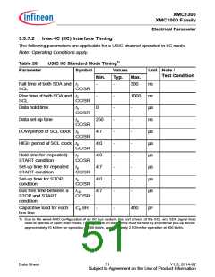
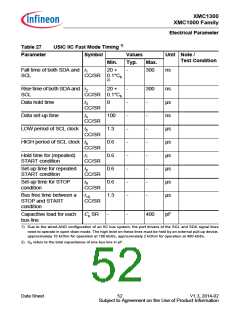
3.3.7.3 Inter-IC Sound (IIS) Interface Timing
The following parameters are applicable for a USIC channel operated in IIS mode.
Note: Operating Conditions apply.
Table 28
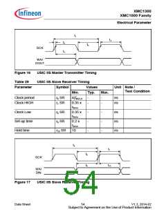
USIC IIS Master Transmitter Timing
Parameter
Symbol
Values
Unit Note /
Test Condition
Min.
Typ.
Max.
Clock period
t1 CC
2/fMCLK
4/fMCLK
-
-
-
-
-
-
ns
ns
ns
VDDP ≥ 3 V
VDDP < 3 V
Clock HIGH
Clock Low
t2 CC
t3 CC
0.35 x
t1min
0.35 x
t1min
-
-
-
ns
Hold time
t4 CC
t5 CC
0
-
-
-
ns
Clock rise time
0.15 x ns
t1min
Data Sheet
53
V1.3, 2014-02
Subject to Agreement on the Use of Product Information

 INFINEON [ Infineon ]