XMC1300
XMC1000 Family
General Device Information
2.2.2
Port I/O Functions
The following general building block is used to describe each PORT pin:
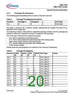
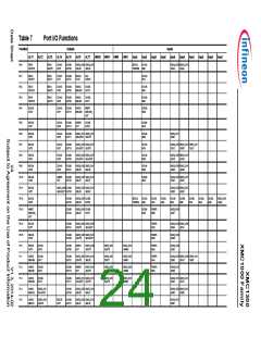
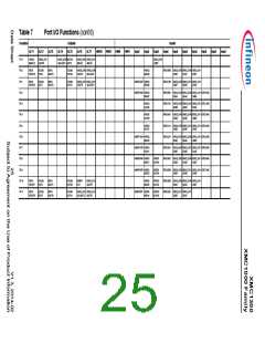
Table 6
Port I/O Function Description
Outputs
Function
Inputs
Input Input
ALT1
ALTn
HWO0
HWI0
P0.0
Pn.y
MODA.OUT MODB.OUT MODB.INA MODC.INA
MODA.INA MODC.INB
MODA.OUT
Pn.y is the port pin name, defining the control and data bits/registers associated with it.
As GPIO, the port is under software control. Its input value is read via Pn_IN.y, Pn_OUT
defines the output value.
Up to seven alternate output functions (ALT1/2/3/4/5/6/7) can be mapped to a single port
pin, selected by Pn_IOCR.PC. The output value is directly driven by the respective
module, with the pin characteristics controlled by the port registers (within the limits of
the connected pad).
The port pin input can be connected to multiple peripherals. Most peripherals have an
input multiplexer to select between different possible input sources.
The input path is also active while the pin is configured as output. This allows to feedback
an output to on-chip resources without wasting an additional external pin.
By Pn_HWSEL, it is possible to select between different hardware “masters”
(HWO0/HWI0, HWO1/HWI1). The selected peripheral can take control of the pin(s).
Hardware control overrules settings in the respective port pin registers.
Data Sheet
23
V1.3, 2014-02
Subject to Agreement on the Use of Product Information

 INFINEON [ Infineon ]