Forced Quasi Resonant ZVS flyback controller
Functional Description
Protection Modes
HV
HV Startup-cell
Auto Restart
Mode
Bang-Bang Ctrl
Closed/Open
Startup-Cell
Driver
VVCCBBoff = 20.5 V
Latch
Mode
VVCCBBonAR/LM = 9 V
D1
Power
Management
VCC
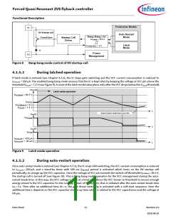
Figure 8
Bang-bang mode control of HV startup-cell
4.1.5.1
During latched operation
If latch mode is entered (see Chapter 4.3.2), the IC stops gate switching and the VCC current consumption is reduced to
IVCCquLM = 150 µA. The enabled bang-bang mode ensures that the IC is kept alive by keeping the voltage at VCC pin above the
threshold VVCCoff = 7.2 V (see Figure 9). A reset of the latch mode takes place only after the VCC drops below the VVCCoff threshold.
VVCC(t)
Latch mode operation
VVCCBBoff = 20.5 V
VVCCSS
VVCCBBonLM = 9 V
VVCCoff = 7.2 V
t
Reset of latch mode due to low VAC
VHV(t)
VVACpeak
t
IVCC(t)
IVCCop
IVCCquLM = 150 µA
IVCCUVOFF = 30 µA
t
Figure 9
Latch mode operation
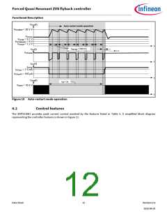
4.1.5.2
During auto-restart operation
Once auto-restart mode is entered (see Chapter 4.3.1), the IC stops GD0 switching, the VCC current consumption is reduced
to IVCCquAR = 160 µA, and a stand-by timer with 500 ms (tBBoffAR) period is activated which turns on the HV startup cell
periodically, to charge up the VCC capacitor. Once the voltage at VCC pin exceeds the switch-off threshold VVCCBBoff = 20.5 V,
the startup cell is turned off (see Figure 10). This is bang-bang mode operation for the VCC management during the auto-
restart break time. In this way, the VCC voltage is kept at a level well above the VCC brown-in threshold to ensure enough
energy stored in the VCC capacitor for the coming restart of the system, that is initiated after the auto-restart break time
tAR = 3 s. Then after an additional time ∆t = ε, the gate driver switching is activated with a soft-start sequence. Here the
additional time ε depends on the VCC capacitor charge-up time which is related to the VCC capacitance and the voltage at
HV pin.
Data Sheet
11
Revision 2.0
2020-08-20

 INFINEON [ Infineon ]