Forced Quasi Resonant ZVS flyback controller
Functional Description
MFIO
C5
burst-on
VMFIOBMWK
BM 2-point
Regulation
Power
Management
BM Ctrl
burst-off
C6
VMFIOBMPA
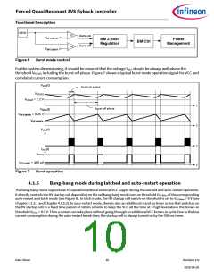
Figure 6
Burst mode control
For the system dimensioning, it should be ensured that the voltage VVCC should be always well above the
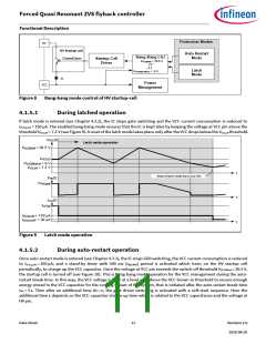
threshold VVCCoff, including the burst-off phase. Figure 7 shows a typical burst mode operation signal for VCC and
correlated current consumption.
VVCC(t)
burst-on phase
VVCCSS
VVCCoff = 7.2 V
t
burst-off phase
VMFIO(t)
VMFIOBMWK = 0.26 V
VMFIOBMPA
t
VGD0(t)
t
IVCC(t)
IVCCop
IVCCquBM2 = 460 µA
t
Figure 7
Burst operation
4.1.5
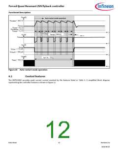
Bang-bang mode during latched and auto-restart operation
The bang-bang mode supports an IC operation without external VCC supply during the latched and auto-restart operation.
It directly controls the HV startup cell depending on the set bang-bang mode turn-on threshold VVCCBBon of the corresponding
auto-restart and latch mode (see Figure 8). In latch mode, the HV startup cell switch-on threshold is set to VVCCBBon = 9 V (see
Chapter 4.1.5.1 and Chapter 4.1.5.2). In auto-restart mode, there is also an additional stand-by timer active that switches on
the HV startup cell in a fixed time period of 500ms scheme to keep the VCC all the time at a high level above the brown-in
threshold VVCCBI = 9.1 V. Then a restart can take place without going through an additional VCC brown-in cycle. Due to the low
current consumption during the auto-restart break time, the startup cell is always turned on by the 500 ms timer.
Data Sheet
10
Revision 2.0
2020-08-20

 INFINEON [ Infineon ]