XC2287 / XC2286 / XC2285
XC2000 Family Derivatives
Preliminary
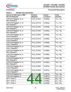
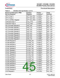
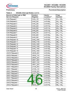
Table 4
Functional Description
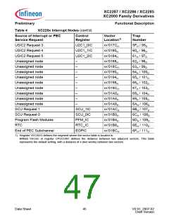
XC228x Interrupt Nodes (cont’d)
Source of Interrupt or PEC
Service Request
Control
Register
Vector
Trap
Number
Location1)
USIC2 Request 3
USIC2 Request 4
USIC2 Request 5
Unassigned node
Unassigned node
Unassigned node
Unassigned node
Unassigned node
Unassigned node
Unassigned node
Unassigned node
Unassigned node
SCU Request 1
U2C1_0IC
xx’017CH
xx’0180H
xx’0184H
xx’0188H
xx’018CH
xx’0190H
xx’0194H
xx’0198H
xx’019CH
xx’01A0H
xx’01A4H
xx’01A8H
xx’01ACH
xx’01B0H
xx’01B4H
xx’01B8H
xx’01BCH
5FH / 95D
60H / 96D
U2C1_1IC
U2C1_2IC
61H / 97D
–
62H / 98D
–
63H / 99D
–
64H / 100D
65H / 101D
66H / 102D
67H / 103D
68H / 104D
69H / 105D
6AH / 106D
6BH / 107D
6CH / 108D
6DH / 109D
6EH / 110D
6FH / 111D
–
–
–
–
–
–
SCU_1IC
SCU_0IC
PFM_IC
RTC_IC
EOPIC
SCU Request 0
Program Flash Modules
RTC
End of PEC Subchannel
1) Register VECSEG defines the segment where the vector table is located to.
Bitfield VECSC in register CPUCON1 defines the distance between two adjacent vectors. This table
represents the default setting, with a distance of 4 (two words) between two vectors.
Data Sheet
45
V0.91, 2007-02
Draft Version

 INFINEON [ Infineon ]