OPTIREG™ SBC TLE9274QXV33
Interrupt function
11
Interrupt function
11.1
Block and functional description
Vcc1
INT
Time
out
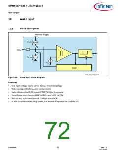
Interrupt logic
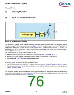
Figure 33 Interrupt block diagram
The interrupt is used to signal wake-up events in real time to the microcontroller. The interrupt block is
designed as a push/pull output stage as shown in Figure 33. An interrupt is triggered and the INT pin is pulled
LOW (active LOW) for tINT in SBC Normal and Stop mode and it is released again once tINT is expired. The
minimum HIGH-time of INT between two consecutive interrupts is tINTD. An interrupt does not automatically
cause a SBC mode change.
The following wake-up events will be signaled via INT:
•
•
•
All wake-up events stored in the wake status SPI register WK_STAT_1 and WK_STAT_2
An interrupt is only triggered if the respective function is also enabled as a wake source
The register WK_LVL_STAT is not generating interrupts
In addition to this behavior, an INT will be triggered when:
•
•
The SBC is sent to SBC Stop mode and not all bits were cleared in the WK_STAT_1 and WK_STAT_2 register
An automatic transition PFM to PWM in the buck when the SBC is in SBC Stop mode (for more details please
refer to Chapter 6.4.2.1)
The SPI status registers are updated at every falling edge of the INT pulse. All interrupt events are stored in the
respective register (except the register WK_LVL_STAT) until the register is read and cleared via SPI command.
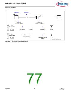
A typical interrupt behavior is shown in Figure 34.
Datasheet
76
Rev.2.0
2022-05-06

 INFINEON [ Infineon ]