OPTIREG™ SBC TLE9274QXV33
High-speed CAN transceiver
The transceiver can also be configured as wake-capable in order to save power and to ensure a safe transition
from SBC Normal to Sleep mode (to avoid losing messages).
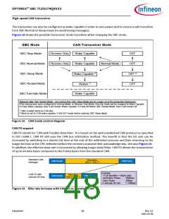
Figure 18 shows the possible transceiver mode transition when changing the SBC mode.
SBC Mode
CAN Transceiver Mode
SBC Stop Mode
Receive Only
Receive Only
Wake Capable
OFF
OFF
SBC Normal Mode
SBC Sleep Mode
SBC Restart Mode
SBC Fail-Safe Mode
Wake Capable
Normal Mode
Wake Capable 2)
OFF 2)
OFF
Woken 1)
Wake Capable
Behavior after SBC Restart Mode - not coming from SBC Sleep Mode due to a wake up of the respective transceiver:
If the transceivers were configured to Normal Mode, or Receive Only Mode, then the mode will be changed to Wake Capable.
If it was Wake Capable, then it will remain Wake Capable. If it was off before SBC Restart Mode, then it will remain off.
1) After a wake event on CAN Bus.
2) Must be set to CAN wake capable / CAN OFF mode before entering SBC Sleep Mode.
Figure 18 CAN mode control diagram
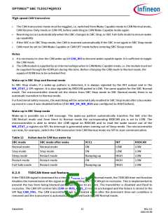
CAN FD support
CAN FD stands for ‘CAN with Flexible Data Rate’. It is based on the well established CAN protocol as specified
in ISO 11898-1. CAN FD still uses the CAN bus arbitration method. The benefit is that the bit rate can be
increased by switching to a shorter bit time at the end of the arbitration process and then returning to the
longer bit time at the CRC delimiter before the receivers transmit their acknowledge bits. See also Figure 19.
In addition, the effective data rate is increased by allowing longer data fields. CAN FD allows the transmission
of up to 64 data bytes compared to the 8 data bytes from the standard CAN.
Standard CAN
message
Data phase
(Byte 0 – Byte 7)
CAN Header
CAN Footer
Example:
- 11 bit identifier + 8Byte data
CAN FD with
reduced bit time
Data phase
(Byte 0 – Byte 7)
CAN Header
CAN Footer
- Arbitration Phase
- Data Phase
500kbps
2Mbps
àaverage bit rate
1.14Mbps
Figure 19 Bite rate increase with CAN FD vs. standard CAN
Datasheet
48
Rev.2.0
2022-05-06

 INFINEON [ Infineon ]