TLE9263QX
High Speed CAN Transceiver
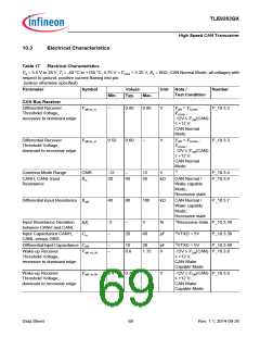
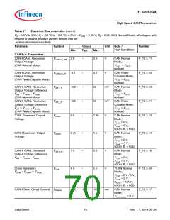
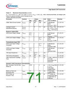
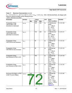
Table 17
Electrical Characteristics (cont’d)
VS = 5.5 V to 28 V; Tj = -40 °C to +150 °C; 4.75 V < VCAN < 5.25 V; RL = 60ꢀ; CAN Normal Mode; all voltages with
respect to ground, positive current flowing into pin
(unless otherwise specified)
Parameter
Symbol
Values
Typ.
2
Unit Note /
Test Condition
Number
Min.
Max.
TXD Permanent Dominant
Time-out
tTxD_CAN_TO
tBUS_CAN_TO
–
–
ms
4)CAN Normal
Mode
P_10.3.36
P_10.3.37
BUS Permanent Dominant
Time-out
–
2
–
ms
4)CAN Normal
Mode
1) Not subject to production test, specified by design.
2) fTXD = 250 kHz rectangular signal, duty cycle = 50%;
3) Rtest between supply (VS / VCAN) and 0V (GND);
4) Not subject to production test, tolerance defined by internal oscillator tolerance;
5) Wake-up is signalized via INT pin activation in SBC Stop Mode and via VCC1 ramping up with wake from SBC Sleep Mode;
6) Time starts with end of last dominant phase of WUP;
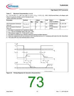
V TXD
V CC1
GND
t
VDIFF
td(L ),T
td(H),T
V diff, rd_N
V diff, dr_N
t
t
t d(L),R
t d(H),R
td(L),TR
t
d(H),TR
V RXD
V CC 1
0.8 x V
CC1
0.2 x VCC1
GND
CAN dynamic characteristics.vsd
Figure 30 Timing Diagrams for Dynamic Characteristics
Data Sheet
73
Rev. 1.1, 2014-09-26

 INFINEON [ Infineon ]