TLE9263QX
High Speed CAN Transceiver
10.3
Electrical Characteristics
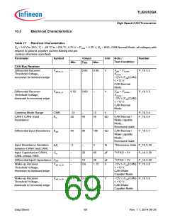
Table 17
Electrical Characteristics
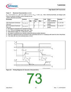
VS = 5.5 V to 28 V; Tj = -40 °C to +150 °C; 4.75 V < VCAN < 5.25 V; RL = 60ꢀ; CAN Normal Mode; all voltages with
respect to ground, positive current flowing into pin
(unless otherwise specified)
Parameter
Symbol
Values
Typ.
Unit Note /
Test Condition
Number
Min.
Max.
CAN Bus Receiver
Differential Receiver
Threshold Voltage,
recessive to dominant edge
Vdiff,rd_N
–
0.80
0.60
0.90
V
V
V
VCANL
-12V ≤ VCM(CAN)
≤ +12 V;
CAN Normal
Mode
diff = VCANH
-
P_10.3.2
;
Differential Receiver
Threshold Voltage,
Vdiff,dr_N
0.50
–
Vdiff = VCANH
-
P_10.3.3
VCANL
;
dominant to recessive edge
-12V ≤ VCM(CAN)
≤ +12 V;
CAN Normal
Mode
1)
Common Mode Range
CMR
-12
20
–
12
50
V
P_10.3.4
P_10.3.6
CANH, CANL Input
Resistance
Rin
40
kꢀ
CAN Normal /
Wake capable
Mode;
Recessive state
Differential Input Resistance Rdiff
40
80
100
kꢀ
CAN Normal /
Wake capable
Mode;
P_10.3.7
Recessive state
Input Resistance Deviation
between CANH and CANL
∆Ri
-3
–
–
3
%
1)Recessive state P_10.3.38
Input Capacitance CANH,
CANL versus GND
Cin
20
40
pF
1)VTXD = 5V
P_10.3.39
DifferentialInputCapacitance Cdiff
–
–
10
20
pF
V
1)VTXD = 5V
P_10.3.40
Wake-up Receiver
Vdiff, rd_W
0.8
1.15
-12V ≤ VCM(CAN) P_10.3.8
≤ +12 V;
Threshold Voltage,
recessive to dominant edge
CAN Wake
Capable Mode
Wake-up Receiver
Threshold Voltage,
Vdiff, dr_W
0.4
0.7
–
V
-12V ≤ VCM(CAN) P_10.3.9
≤ +12 V;
dominant to recessive edge
CAN Wake
Capable Mode
Data Sheet
69
Rev. 1.1, 2014-09-26

 INFINEON [ Infineon ]