TDA5235
Functional Description
2.4.6.2 FSK Demodulator
The limiter output signal, which has a constant amplitude over a wide range of the input
signal, feeds the FSK demodulator. There is a configurable lowpass filter in front of the
FSK demodulation to suppress the down conversion image and noise/limiter harmonics
(FSK Pre-Demodulation Filter, PDF). This is realized as a 3rd order digital filter. The
sampling rate after FSK demodulation is fixed and independent from the target data rate.
2.4.6.3 Automatic Frequency Control Unit (AFC)
In front of the image suppression filter a second FSK demodulator is used to derive the
control signal for the Automatic Frequency Control Unit, which is actually the DC
value of the FSK demodulated signal. This makes the AFC loop independent from signal
path filtering and allow so a wider frequency capture range of the AFC. The derivation of
the AFC control signal is preferably done during the DC free preamble and is then frozen
for the rest of the datagram.
Since the digital FSK demodulator determines the exact frequency offset between the
received input frequency and the programmed input center frequency of the receiver,
this offset can be corrected through the sigma delta control of the PLL. As shown in
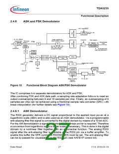
Figure 10, for AFC purposes a parallel demodulation path is implemented. This path
does not contain the digital low pass filter (PDF, Pre-Demodulation Filter). The entire IF
bandwidth, filtered by the analog bandpass filter only, is processed by the AFC
demodulator.
There are two options for the active time of the AFC loop:
• 1. always on
• 2. active for a programmable time relative to a signal identification event (several
options can be programmed in SFR).
In the latter case the AFC can either be started or frozen relative to the signal
identification. After the active time the offset for the sigma-delta PLL (SD PLL) is frozen.
The programming of the active time is especially necessary in case the expected frame
structure contains a gap (noise) between wake-up and payload in order to avoid the AFC
from drifting.
AFC works both for FSK and ASK. In the latter case the AFC loop only regulates during
ASK data = high.
The maximum frequency offset generated by the AFC can be limited by means of the
x_AFCLIMIT register. This limit can be used to avoid the AFC from drifting in the
presence of interferers or when no RF input signal is available (AFC wander). A
maximum AFC limit of 42 kHz is recommended. AFC wandering needs to be kept in mind
especially when using Run Mode Slave.
Data Sheet
28
V1.0, 2010-02-19

 INFINEON [ Infineon ]