TDA5235
Functional Description
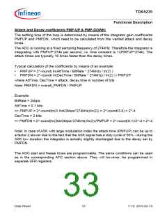
K1 = integrator1 gain
x_AFCLIMIT
x_AFCK1CFG0/1
integrator1
SDPLL
scaling &
limiting
FreqOffset
AFC Demod out
limit
K1
x16
HOLD
integrator2
hold
limit
hold
K2
x4
Freeze* / Track
Delay
x_AFCK2CFG0/1
x_AFCAGCD
K2 = integrator 2 gain
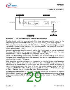
Figure 11
AFC Loop Filter (I-PI Filtering and Mapping)
The bandwidth (and thus settling time) of the loop is programmed by means of the
integrator gain coefficients K1 and K2 (x_AFCK1CFG and x_AFCK2CFG register).
K1 mainly determines the bandwidth. K2 influences the dynamics/damping (overshoot)
- smaller K2 means smaller overshoot, but slower dynamics. The bandwidth of the AFC
loop is approximately 1.3*K1.
To avoid residual FM, limiting the AFC BW to 1/20 ~ 1/40 of the bit rate is suggested,
therefore K1 must be set to approximately 1/50 ~ 1/100 of the bit rate. For most
applications K2 can be set equal to K1 (overshoot is then <25%).
When very fast settling is necessary K1 and K2 can be increased up to bit rate/10,
however, in this case approximately 1dB sensitivity loss is to be expected due to the AFC
counteracting the input FSK signal.
AFC limitation at Local Oscillator (LO) frequencies at multiples of reference frequency
(f_xtal). When AFC is activated and AFC drives the wanted LO frequency over the
integer limit of Sigma Delta (SD) modulator, the SD modulator stucks at frac=1.0 or
frac=0.0 due to saturation. So when AFC can change the integer value for the LO
(register x_PLLINTC1) within the frequency range LO-frequency +/- AFC-limit, a change
of the LO injection side or a smaller AFC-limit is recommended.
The frequency offset found by AFC (AFC loop filter output) can be readout via register
AFCOFFSET, when AFC is activated. The value is in signed representation and has a
frequency resolution of 2.68 kHz/digit. The output can be limited by the x_AFCLIMIT
register.
Data Sheet
29
V1.0, 2010-02-19

 INFINEON [ Infineon ]