TDA 5210
preliminary
Reference
Q2
SFE10.7MA5-A or
SKM107M1-A20-10
Murata
Toko
X2, X3
142-0701-801
Johnson
S1-S3, S6
X1, X3
2-pole pin connector
S4
3-pole pin connector, or not equipped
Infineon
IC1
TDA 5210
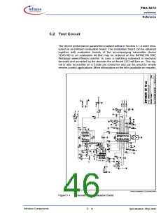
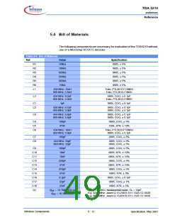
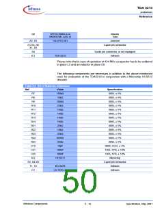
Please note that in case of operation at 434 MHz a capacitor has to be soldered
in place L2 and an inductor in place C6.
The following components are necessary in addition to the above mentioned
ones for evaluation of the TDA5210 in conjunction with a Microchip HCS512
decoder.
Table 5-6 Bill of Materials Addendum
Ref
Value
100kΩ
10kΩ
Specification
0805, ± 5%
R7
R8
0805, ± 5%
R9
100kΩ
22kΩ
0805, ± 5%
R10
R11
R12
R13
R14
R21
R22
R23
R24
R25
C19
C21
C22
IC2
0805, ± 5%
100Ω
100Ω
100Ω
100Ω
22kΩ
0805, ± 5%
0805, ± 5%
0805, ± 5%
0805, ± 5%
0805, ± 5%
10kΩ
0805, ± 5%
22kΩ
0805, ± 5%
820kΩ
560Ω
10pF
0805, ± 5%
0805, ± 5%
0805, COG, ± 5%
1206, X7R, ± 10%
1206, X7R, ± 10%
Microchip
100nF
100nF
HCS512
S5, X4-X9
T1, T2
D1
2-pole pin connector
Infineon
BC 847B
LS T670-JL
Infineon
Wireless Components
5 - 16
Specification, May 2001

 INFINEON [ Infineon ]