TC1796
Functional Description
3.17
System Timer
The TC1796’s STM is designed for global system timing applications requiring both high
precision and long range.
Features
•
•
•
•
•
•
•
Free-running 56-bit counter
All 56 bits can be read synchronously
Different 32-bit portions of the 56-bit counter can be read synchronously
Flexible interrupt generation based on compare match with partial STM content
Driven by max. 75 MHz (= fSYS, default after reset = fSYS/2)
Counting starts automatically after a reset operation
STM is reset by:
– Watchdog reset
– Software reset (RST_REQ.RRSTM must be set)
– Power-on reset
•
•
STM is not reset at a hardware reset
STM can be halted in debug/suspend mode
The STM is an upward counter, running either at the system clock frequency fSYS or at a
fraction of it. In case of a power-on reset, a watchdog reset, or a software reset, the STM
is reset. After one of these reset conditions, the STM is enabled and immediately starts
counting up. It is not possible to affect the contents of the timer during normal operation
of the TC1796. The timer registers can only be read but not written to. The STM can be
optionally disabled or suspended for power-saving and debugging purposes via its clock
control register. In suspend mode of the TC1796, the STM clock is stopped but all
registers are still readable.
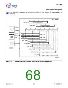
The System Timer can be read in sections from seven registers, STM_TIM0 through
STM_TIM6, which select increasingly higher-order 32-bit ranges of the System Timer.
These can be viewed as individual 32-bit timers, each with a different resolution and
timing range. For getting a synchronous and consistent reading of the complete STM
contents, a capture register (STM_CAP), is implemented. It latches the contents of the
high part of the STM each time when one of the registers STM_TIM0 to STM_TIM5 is
read. Thus, it holds the upper value of the timer at exactly the same time when the lower
part is read. The second read operation would then read the contents of the STM_CAP
to get the complete timer value.
The content of the 56-bit System Timer can be compared against the content of two
compare values stored in the compare registers. Interrupts can be generated on a
compare match of the STM with the STM_CMP0 or STM_CMP1 registers.
The maximum clock period is 256 × fSTM. At fSTM = 75 MHz, for example, the STM counts
30.47 years before overflowing. Thus, it is capable of continuously timing the entire
expected product life-time of a system without overflowing.
Data Sheet
67
V1.0, 2008-04

 INFINEON [ Infineon ]