TC1796
Functional Description
3.12
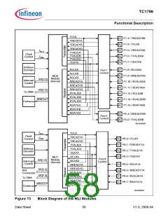
MultiCAN Controller (CAN)
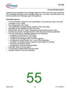
Figure 11 shows a global view of the MultiCAN module with its functional blocks and
interfaces.
fCAN
MultiCAN Module Kernel
CAN
P6.15 /
TXDCAN3
P6.14 /
RXDCAN3
Clock
Control
A2
A2
fCLC
TXDC3
RXDC3
Node 3
Address
Decoder
P6.13 /
TXDCAN2
P6.12 /
RXDCAN2
TXDC2
RXDC2
A2
A2
Message
Object
Buffer
CAN
Node 2
Linked
List
Control
Port 6
Control
DMA
TXDC1
RXDC1
CAN
Node 1
128
Objects
P6.11 /
TXDCAN1
P6.10 /
RXDCAN1
A2
A2
INT_O
[3:0]
Interrupt
Control
TXDC0
RXDC0
CAN
Node 0
INT_O
[15:4]
P6.9 /
TXDCAN0
P6.8 /
RXDCAN0
A2
A2
INT_
O15
LTCA2
GPTA1
GPTA0
CAN Control
Timing Control and Synchronization
ECTT1
ECTT2
P1.3 /
REQ3
P7.5 /
REQ7
ECTT3
A1
A1
Scheduler
ECTT4
ECTT5
ScheduleTiming DataMemory
SCU
Ext.Req.
Unit
Time-Triggered Extension TTCAN
MCA05864
Figure 11
Block Diagram of MultiCAN Module with Time-Triggered Extension
The MultiCAN module contains four independently operating CAN nodes with Full-CAN
functionality that are able to exchange Data and Remote Frames via a gateway function.
Transmission and reception of CAN frames is handled in accordance with CAN
specification V2.0 B (active). Each CAN node can receive and transmit standard frames
with 11-bit identifiers as well as extended frames with 29-bit identifiers.
All four CAN nodes share a common set of message objects. Each message object can
be individually allocated to one of the CAN nodes. Besides serving as a storage
container for incoming and outgoing frames, message objects can be combined to build
gateways between the CAN nodes or to setup a FIFO buffer.
The message objects are organized in double-chained linked lists, where each CAN
node has it’s own list of message objects. A CAN node stores frames only into message
Data Sheet
54
V1.0, 2008-04

 INFINEON [ Infineon ]