TC1767
Electrical Parameters
5.3.4
Power, Pad and Reset Timing
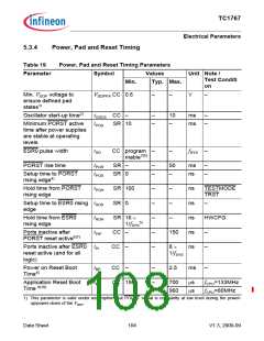
Table 19
Power, Pad and Reset Timing Parameters
Parameter
Symbol
Values
Typ. Max.
Unit Note /
Test Conditi
on
Min.
Min. VDDP voltage to
ensure defined pad
states1)
V
DDPPA CC 0.6
–
–
V
–
Oscillator start-up time2)
tOSCS CC –
tPOA SR 10
–
–
10
–
ms
ms
–
–
Minimum PORST active
time after power supplies
are stable at operating
levels
ESR0 pulse width
tHD
CC program –
mable3)5)
–
fSYS
–
PORST rise time
tPOR
tPOS
SR –
SR 0
–
–
50
–
ms
ns
–
–
Setup time to PORST
rising edge4)
Hold time from PORST
rising edge
tPOH
SR 100
SR 0
–
–
–
–
–
–
ns
ns
ns
ns
ns
TESTMODE
TRST
Setup time to ESR0 rising tHDS
edge
–
–
Hold time from ESR0
rising edge
tHDH
tPIP
SR 16 ×
1/fSYS
–
HWCFG
5)
Ports inactive after
CC –
150
–
–
PORST reset active6)7)
Ports inactive after ESR0 tPI
reset active (and for all
logic)
CC –
8 ×
1/fSYS
Power on Reset Boot
Time8)
tBP
CC –
–
–
2.5
ms
–
Application Reset Boot
Time 9)10)
tB
CC 150
700
960
µs
µs
f
f
CPU=133MHz
CPU=80MHz
1) This parameter is valid under assumption that PORST signal is constantly at low level during the power-
up/power-down of the VDDP
.
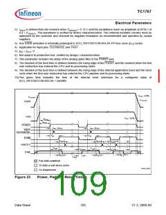
Data Sheet
104
V1.3, 2009-09

 INFINEON [ Infineon ]