C167CR
C167SR
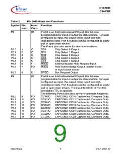
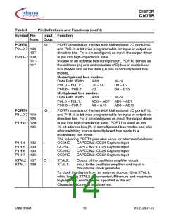
Table 2
Pin Definitions and Functions (cont’d)
Symbol Pin
Input Function
Num. Outp.
P7
IO
Port 7 is an 8-bit bidirectional I/O port. It is bit-wise
programmable for input or output via direction bits. For a pin
configured as input, the output driver is put into high-
impedance state. Port 7 outputs can be configured as push/
pull or open drain drivers. The input threshold of Port 7 is
selectable (TTL or special).
The following Port 7 pins also serve for alternate functions:
P7.0
P7.1
P7.2
P7.3
P7.4
P7.5
P7.6
P7.7
19
20
21
22
23
24
25
26
O
O
O
O
I/O
I/O
I/O
I/O
POUT0
POUT1
POUT2
POUT3
CC28IO
CC29IO
CC30IO
CC31IO
PWM Channel 0 Output
PWM Channel 1 Output
PWM Channel 2 Output
PWM Channel 3 Output
CAPCOM2: CC28 Capture Inp./Compare Outp.
CAPCOM2: CC29 Capture Inp./Compare Outp.
CAPCOM2: CC30 Capture Inp./Compare Outp.
CAPCOM2: CC31 Capture Inp./Compare Outp.
P5
I
Port 5 is a 16-bit input-only port with Schmitt-Trigger
characteristic.
The pins of Port 5 also serve as analog input channels for the
A/D converter, or they serve as timer inputs:
P5.0
P5.1
P5.2
P5.3
P5.4
P5.5
P5.6
P5.7
27
28
29
30
31
32
33
34
35
36
39
40
41
42
43
44
I
I
I
I
I
I
I
I
I
I
I
I
I
I
I
I
AN0
AN1
AN2
AN3
AN4
AN5
AN6
AN7
AN8
AN9
AN10,
AN11,
AN12,
AN13,
AN14,
AN15,
P5.8
P5.9
P5.10
P5.11
P5.12
P5.13
P5.14
P5.15
T6EUD GPT2 Timer T6 Ext. Up/Down Ctrl. Inp.
T5EUD GPT2 Timer T5 Ext. Up/Down Ctrl. Inp.
T6IN
T5IN
GPT2 Timer T6 Count Inp.
GPT2 Timer T5 Count Inp.
T4EUD GPT1 Timer T4 Ext. Up/Down Ctrl. Inp.
T2EUD GPT1 Timer T5 Ext. Up/Down Ctrl. Inp.
Data Sheet
6
V3.2, 2001-07

 INFINEON [ Infineon ]