SAE 81C90/91
07Feb95@09:05h Intermediate Version
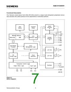
Bus communication is based on the controller-area-network (CAN) protocol. With features like short
message length, guaranteed reaction time for messages of appropriate priority, which is defined by
the message identifiers. Also included are powerful error detection and treatment capabilities plus
ease of operation. The CAN protocol is especially designed for the requirements of automobile and
industrial electronic networks.
The SFCAN circuit incorporates all the parts for completely independent transmission and reception
of messages using the CAN protocol. The flexible, programmable interface allows connection to
different implementations of the physical layer. The link to a host controller can be made either by
a multiplexed 8-bit address/data bus or by a high-speed, serial synchronous interface.
Message Memory
The SFCAN circuit filters incoming messages with an associative memory (CAM = content-
addressable memory). For this the identifier and RTR bits of the required message must be written
to the appropriate memory location.
The identifier of each incoming message is compared with the identifiers stored in the CAM. Upon
a match the received data bytes are written into the RAM buffer of the matching message. At the
same time the corresponding receive-ready bit is set and a receive interrupt is generated, if it is
enabled. If no match is detected, the received message is rejected.
Identifiers can be reprogrammed at any time, although it is possible that data of the old or new
identifier may be lost during reprogramming.
An incoming transmit request will only be satisfied automatically by the hardware if the RTR bit of
the particular identifier is set in CAM.
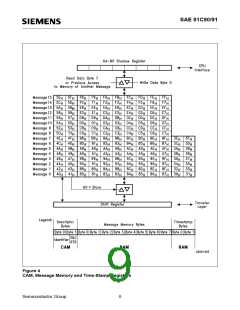
To ensure data consistency when reading or writing several data bytes of a specific message the
message objects are not accessed directly but via a 64-bit shadow register (see figure below).
This shadow register stores the complete data field of a certain message object for both reading and
writing.
For read accesses the message’s data field is copied to the shadow register...
...with the 1st read access to the respective data field (e.g. 80 ... 87 for message 0), or
H
H
...with any read access to byte 7 of the respective data field (e.g. 87 for message 0).
H
This ensures that all bytes read via the shadow register belong to the same message, even though
a new one might have been received in the meantime.
For write accesses the shadow register is copied to the respective message data field...
...with any write access to byte 0 of the respective data field (e.g. 80 for message 0).
H
This ensures that only completely updated message are transmitted.
It is therefore recommended to begin all read and write accesses with the most-significant data byte
of a message and end with data byte 0. This ensures operations on consistent data and correct
transfers between the shadow register and the message RAM.
Note: For these reasons it is absolutely essential to ensure that the writing of data is not interrupted
by a read operation and vice versa, a read operation should not be interrupted by a write.
Semiconductor Group
7

 INFINEON [ Infineon ]