SAE 81C90/91
07Feb95@09:05h Intermediate Version
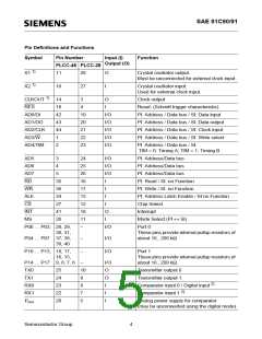
Pin Definitions and Functions (cont’d)
Symbol
Pin Number
Input (I)
Function
Output (O)
PLCC-48 PLCC-28
VSSA
21
6
I
Analog power ground for comparator
(must always be connected)
3)
VDD1
VDD2
VSS1
VSS2
13
32
12
33
2
I
I
I
I
Digital power supply
13
1
Digital power supply
3)
Digital power ground
14
Digital power ground
1)
For best results keep the crystal circuitry connections as short as possible and keep the CLKOUT
line away from it.
2)
3)
If the bus lines work according to the ISO specification, additional circuitry is necessary for
interconnection of the input comparator to the bus lines.
The digital mode is enabled by setting bit DI in register BL2. When using the digital mode pin RX1
should be on V .
SS
It is recommended to decouple these supply pins close to the device using a 10 pF capacitor in
addition to the standard 100 nF capacitor.
Semiconductor Group
5

 INFINEON [ Infineon ]