SAE 81C90/91
07Feb95@09:05h Intermediate Version
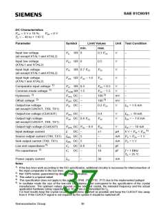
DC Characteristics
CC = 5 V ± 10 %;
V
VSS = 0 V
TA = – 40 to + 110 ˚C
Parameter
Symbol
Limit Values
max.
Unit Test Condition
min.
Input low voltage
(all except XTAL1 and XTAL2)
VIL SR 0
0.3 VCC
V
V
V
V
–
–
–
–
Input low voltage
(XTAL1 and XTAL2)
VILX SR 0
0.5
Input high voltage
(all except XTAL1 and XTAL2)
VIH SR 0.7 VCC
VCC
Input high voltage
VIHX SR VCC – 1.0 VCC
(XTAL1 and XTAL2)
1)
Comparator input voltage
VCI SR 0.5
ICOM SR 1.5
V
V
CC + 0.5
V
–
2)
Common mode voltage
V
CC – 1.5
V
–
2)
3)
Hysteresis
VHYS DC –
VOFF DC –
VOL DC –
100
100
mV
mV
V
–
2)
3)
Offset voltage
–
Output low voltage
0.2 VCC
IOL = 1.6 mA
(all except CLKOUT, TX0, TX1)
Output low voltage (CLKOUT)
VOLC DC –
0.4
V
V
I
OL1 = 10 mA
Output high voltage
VOH DC 0.8 VCC
VCC
IOH = – 1.6 mA
(all except CLKOUT, TX0, TX1)
Output high voltage (CLKOUT)
Input leakage current
VOHC DC VCC – 0.8 VCC
V
I
OH = – 10 mA
4)
II
DC –
±1
–
µA
mA
mA
pF
pF
0 V < VIN < VCC
VO = VCC – 1 V
VO = 1 V
Source output current (TX0, TX1) ISRC DC 5
Sink output current (TX0, TX1)
ISNK DC 5
CL DC 6.8
CI DC –
–
5)
Low end capacitance
12
10
2)
Pin capacitance
f = 1 MHz
TA = 25 ˚C
Power supply current
ICC
–
30
mA
Notes
1)
If the bus lines work according to the ISO specification, additional circuitry is necessary for interconnection of
the input comparator to the bus lines.
2)
3)
4)
5)
Not 100% tested, guaranteed by design characterization.
This value is a typical value!
This specification does not apply to the port pins (P00...P07, P10...P17) due to the implemented pullups!
In oscillator mode the size of the low-end capacitance must correspond to the specification of the crystal
manufacturer. The optimum values depend on the selected crystal, the intended frequency and the actual
application hardware (stray capacitances). 10 pF are recommended for C .
L
For best results keep the crystal circuitry connections as short as possible and keep the CLKOUT line away
from it. If the CLKOUT signal is not required by the system it should be switched off.
Semiconductor Group
36

 INFINEON [ Infineon ]