SAB 80C515/80C535
Interrupt Structure
The SAB 80C515 has 12 interrupt vectors with the following vector addresses and request
flags:
Table 3
Interrupt Sources and Vectors
Source (Request Flags)
Vector Address
0003
Vector
IE0
TF0
IE1
TF1
RI + TI
TF2 + EXF2
IADC
IEX2
IEX3
IEX4
IEX5
IEX6
External interrupt 0
Timer 0 interrupt
External interrupt 1
Timer 1 interrupt
Serial port interrupt
Timer 2 interrupt
A/D converter interrupt
External interrupt 2
External interrupt 3
External interrupt 4
External interrupt 5
External interrupt 6
H
000B
H
H
0013
001B
H
H
0023
002B
H
0043
H
004B
H
H
0053
005B
H
H
0063
006B
H
Each interrupt vector can be individually enabled/disabled. The minimum response time to an
interrupt request is more than 3 machine cycles and less than 9 machine cycles.
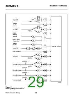
Figure 5 shows the interrupt request sources.
External interrupts 0 and 1 can be activated by a low-level or a negative transition (selectable)
at their corresponding input pin, external interrupts 2 and 3 can be programmed for triggering
on a negative or a positive transition. The external interrupts 3 or 6 are combined with the
corresponding alternate functions compare (output) and capture (input) on port 1.
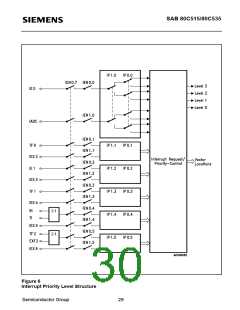
For programming of the priority levels the interrupt vectors are combined to pairs. Each pair can
be programmed individually to one of four priority levels by setting or clearing one bit in the
special function register IP0 and one in IP1.
Figure 6 shows the priority level structure.
Semiconductor Group
27

 INFINEON [ Infineon ]