CoolSET®-F3R
ICE3BR0665JF
Functional Description
3
Functional Description
All values which are used in the functional description condition which could otherwise lead to a destruction of
are typical values. For calculating the worst cases the the SMPS over time. Once the malfunction is removed,
min/max values which can be found in section 4 normal operation is automatically recovered after the
Electrical Characteristics have to be considered.
next Start Up Phase.
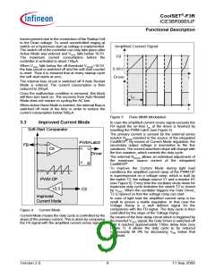
The internal precise peak current limitation reduces the
costs for the transformer and the secondary diode. The
influence of the change in the input voltage on the
power limitation can be avoided together with the
3.1
Introduction
CoolSET®-F3R FullPak is the further development of
the CoolSET®-F3 for high power application. The
particular enhanced features are built-in features for
soft start, blanking window and frequency jitter. It also
provides the flexibility to increase the blanking window
by simply adding capacitance in BA pin. However, the
proven outstanding features in CoolSET®-F3 are
remained.
integrated
Propagation
Delay
Compensation.
Therefore the maximum power is nearly independent
on the input voltage which is required for wide range
SMPS. There is no need for an extra over-sizing of the
SMPS, e.g. the transformer or the secondary diode.
Furthermore, this full package version implements the
frequency jitter mode to the switching clock such that
the EMI noise will be effectively reduced.
The intelligent Active Burst Mode at Standby Mode can
effectively obtain the lowest Standby Power at
minimum load and no load condition. After entering the
burst mode, there is still a full control of the power
conversion by the secondary side via the same
optocoupler that is used for the normal PWM control.
The response on load jumps is optimized. The voltage
ripple on Vout is minimized. Vout is on well controlled in
this mode.
3.2
Power Management
Drain
VCC
Startup Cell
The usually external connected RC-filter in the
feedback line after the optocoupler is integrated in the
IC to reduce the external part count.
CoolMOS®
Furthermore a high voltage Startup Cell is integrated
into the IC which is switched off once the Undervoltage
Lockout on-threshold of 18V is exceeded. This Startup
Cell is part of the integrated CoolMOS®. The external
startup resistor is no longer necessary as this Startup
Cell is connected to the Drain. Power losses are
therefore reduced. This increases the efficiency under
light load conditions drastically.
Power Management
Internal Bias
Undervoltage Lockout
18V
10.5V
5.0V
Voltage
Power-Down Reset
Reference
This version is adopting the BiCMOS technology and it
can increase design flexibility as the Vcc voltage range
is increased to 25V.
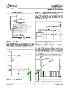
For this full package version, the soft start is a built-in
function. It is set at 20ms. Then it can save external
component counts.
Auto Restart
Mode
Soft Start block
Active Burst
Mode
There are 2 modes of blanking time for high load
jumps; the basic mode and the extendable mode. The
blanking time for the basic mode is pre-set at 20ms
while the extendable mode will increase the blanking
time at basic mode by adding external capacitor at the
BA pin. During this time window the overload detection
is disabled. With this concept no further external
components are necessary to adjust the blanking
window.
In order to increase the robustness and safety of the
system, the IC provides Auto Restart protection mode.
The Auto Restart Mode reduces the average power
conversion to a minimum under unsafe operating
conditions. This is necessary for a prolonged fault
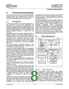
Figure 3
Power Management
The Undervoltage Lockout monitors the external
supply voltage VVCC. When the SMPS is plugged to the
main line the internal Startup Cell is biased and starts
to charge the external capacitor CVCC which is
connected to the VCC pin. This VCC charge current is
controlled to 0.9mA by the Startup Cell. When the VVCC
exceeds the on-threshold VCCon=18V the bias circuit
are switched on. Then the Startup Cell is switched off
by the Undervoltage Lockout and therefore no power
Version 2.0
8
11 Sep 2008

 INFINEON [ Infineon ]