CCM-PFC
ICE2PCS06/G
Electrical Characteristics
4.3
Characteristics
Note:
The electrical characteristics involve the spread of values within the specified supply voltage and junction
temperature range TJ from – 40 °C to 125°C.Typical values represent the median values, which are
related to 25°C. If not otherwise stated, a supply voltage of VCC =18V is assumed for test condition.
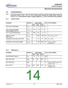
4.3.1
Supply Section
Parameter
Symbol
Limit Values
Unit Test Condition
min.
typ.
max.
VCC Turn-On Threshold
VCCon
11.4
11.8
12.7
11.7
1.4
V
V
V
VCC Turn-Off Threshold/
Under Voltage Lock Out
VCCUVLO
VCChy
ICCstart
ICCHG
10.4
11.0
0.8
VCC Turn-On/Off Hysteresis
0.65
Start Up Current
Before VCCon
-
-
450
10
1100 mA
VVCC=VVCCon -0.1V
Operating Current with active GATE
13
mA CL= 2.2nF
Operating Current during Standby
ICCStdby
-
700
1300 mA
VVSENSE= 0.5V
VICOMP= 4V
4.3.2
PWM Section
Parameter
Symbol
Limit Values
Unit Test Condition
min.
typ.
max.
Fixed Oscillator Frequency
Max. Duty Cycle
Min. Duty Cycle
fSW
58
65
70
98.5
0
kHz
DMAX
DMIN
92
95
%
%
VVCOMP= 0V, VVSENSE= 3V
VICOMP= 4.3V
Min. Off Time
TOFFMIN
270
400
770
ns
VVSENSE= 3V
VISENSE= 0.1V
Version 1.1
14
Mar 2010

 INFINEON [ Infineon ]