™
PROFET + 24V
BTT6200-4ESA
Pin configuration
3
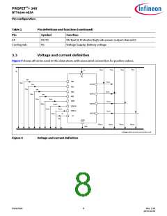
Pin configuration
3.1
Pin assignment
NC
IN0
NC
GND
IN1
DEN
IS
DSEL0
IN2
IN3
DSEL1
NC
1
2
3
4
5
6
7
8
24
23
22
21
20
19
18
17
16
15
14
13
OUT0
NC
NC
NC
OUT1
NC
NC
OUT2
NC
NC
NC
OUT3
9
10
11
12
PG-TSDSO-24-21_Pinout.vsd
Figure 3
Pin configuration
3.2
Pin definitions and functions
Table 2
Pin
Pin definitions and functions
Symbol
Function
1, 3, 12, 14, 15, 16,
18, 19 , 21, 22, 23
NC
Not Connected; No internal connection to the chip
2
4
5
6
IN0
INput channel 0; Input signal for channel 0 activation
GrouND; Ground connection
GND
IN1
INput channel 1; Input signal for channel 1 activation
DEN
Diagnostic ENable; Digital signal to enable/disable the diagnosis of
the device
7
8
IS
Sense; Sense current of the selected channel
DSEL0
Diagnostic SELection; Digital signal to select the channel to be
diagnosed
9
IN2
INput channel 2; Input signal for channel 2 activation
INput channel 3; Input signal for channel 3 activation
10
11
IN3
DSEL1
Diagnostic SELection; Digital signal to select the channel to be
diagnosed
13
17
20
OUT3
OUT2
OUT1
OUTput 3; Protected high side power output channel 3
OUTput 2; Protected high side power output channel 2
OUTput 1; Protected high side power output channel 1
Datasheet
7
Rev. 1.00
2019-03-09

 INFINEON [ Infineon ]