®
PROFET BTS 740 S2
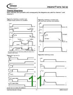
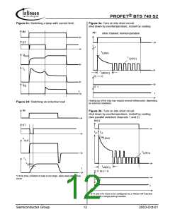
Timing diagrams
Both channels are symmetric and consequently the diagrams are valid for channel 1 and
channel 2
Figure 1a: Switching a resistive load,
Figure 2a: Switching a resistive load,
change of load current in on-condition:
turn-on/off time and slew rate definition:
IN
IN
ST
t
don(ST)
t
VOUT
doff(ST)
V
90%
OUT
t
dV/dtoff
t
on
on
t
off
t
dV/dton
t
t
I
I
slc(IS)
slc(IS)
off
L
10%
Load 1
IL
Load 2
t
IS
t
son(IS)
t
soff(IS)
t
The sense signal is not valid during settling time after turn or
change of load current.
Figure 2b: Switching a lamp:
Figure 1b: V turn on:
bb
IN1
IN
IN2
ST
V
bb
V
OUT1
VOUT
V
OUT2
IL
ST1 open drain
ST2 open drain
t
t
proper turn on under all conditions
Semiconductor Group
11
2003-Oct-01

 INFINEON [ Infineon ]