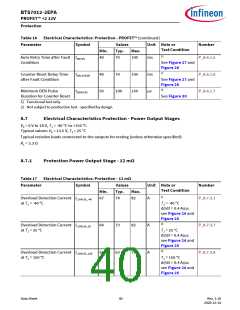
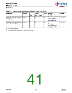
BTS7012-2EPA
PROFET™ +2 12V
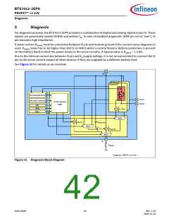
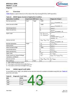
Diagnosis
9.2
Diagnosis in ON state
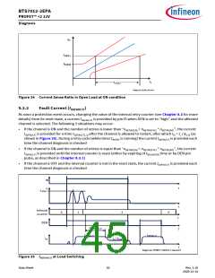
A current proportional to the load current (ratio kILIS = IL / IIS) is provided at pin IS when the following conditions
are fulfilled:
•
•
•
The power output stage is switched ON with VDS < VDS(OLOFF)
The diagnosis is enabled for that channel
No fault (as described in Chapter 8.3) is present or was present and not cleared yet (see Chapter 9.2.2 for
further details)
If a “hard” failure mode is present or was present and not cleared yet a current IIS(FAULT) is provided at IS pin.
9.2.1
Current Sense (kILIS)
The accuracy of the sense current depends on temperature and load current. IIS increases linearly with IL
output current until it reaches the saturation current IIS(SAT). In case of Open Load at the output stage (IL close
to 0 A), the maximum sense current IIS(EN) (no load, diagnosis enabled) is specified. This condition is shown in
Figure 34. The blue line represents the ideal kILIS line, while the red lines show the behavior of a typical
product.
An external RC filter between IS pin and microcontroller ADC input pin is recommended to reduce signal ripple
and oscillations (a minimum time constant of 1 µs for the RC filter is recommended).
The kILIS factor is specified with limits that take into account effects due to temperature, supply voltage and
manufacturing process. Tighter limits are possible (within a defined current window) with calibration:
•
•
•
A well-defined and precise current (IL(CAL)) is applied at the output during End of Line test at customer side
The corresponding current at IS pin is measured and the kILIS is calculated (kILIS @ IL(CAL)
)
Within the current range going from IL(CAL)_L to IL(CAL)_H the kILIS is equal to kILIS @ IL(CAL) with limits defined by
ΔkILIS
The derating of kILIS after calibration is calculated using the formulas in Figure 33 and it is specified by ΔkILIS
Diagnosis_dKILIS.emf
Figure 33 ΔkILIS calculation formulas
The calibration is intended to be performed at TA(CAL) = 25°C. The parameter ΔkILIS includes the drift
overtemperature as well as the drift over the current range from IL(CAL)_L to IL(CAL)_H
.
Data Sheet
44
Rev. 1.10
2020-12-14

 INFINEON [ Infineon ]