BTS7012-2EPA
PROFET™ +2 12V
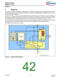
Diagnosis
9.1
Overview
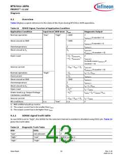
Table 18 gives a quick reference to the state of the IS pin during BTS7012-2EPA operation.
Table 18 SENSE Signal, Function of Application Condition
Application Condition
Input level DEN level VOUT
Diagnostic Output
Normal operation
“low”
“high”
~ GND
Z
IIS(FAULT) if counter > 0
Short circuit to GND
~ GND
Z
IIS(FAULT) if counter > 0
Overtemperature
Z
IIS(FAULT)
Short circuit to VS
VS
IIS(OLOFF)
(IIS(FAULT) if counter > 0)
Open Load
< VS - VDS(OLOFF)
> VS - VDS(OLOFF)
Z
1)
IIS(OLOFF)
(in both cases IIS(FAULT) if
counter > 0)
Inverse current
~ VINV = VOUT > VS IIS(OLOFF)
(IIS(FAULT) if counter > 0)
Normal operation
Overcurrent
“high”
~ VS
< VS
~ GND
Z
IIS = IL / kILIS
IIS(FAULT)
Short circuit to GND
Overtemperature
Short circuit to VS
Open Load
IIS(FAULT)
IIS(FAULT)
VS
IIS < IL / kILIS
IIS = IIS(EN)
2)
~ VS
3)
Under load (e.g. Output Voltage
Limitation condition)
~ VS
IIS(EN) < IIS < IL(NOM) / kILIS
Inverse current
~ VINV = VOUT > VS IIS = IIS(EN)
n.a.
All conditions
n.a.
“low”
Z
1) With additional pull-up resistor.
2) The output current has to be smaller than IL(OL)
3) The output current has to be higher than IL(OL)
.
.
9.1.1
SENSE signal truth table
In case DEN is set to “high”, the SENSE for the selected channel is enabled or disabled using DSEL pin. Table 19
gives the truth table.
Table 19 Diagnostic Truth Table
DEN
DSEL
IS
“low”
“high”
“high”
not relevant
“low”
Z
SENSE output 0
SENSE output 1
“high”
Data Sheet
43
Rev. 1.10
2020-12-14

 INFINEON [ Infineon ]