BFP640
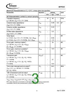
Electrical Characteristics at T = 25°C, unless otherwise specified
Parameter
Symbol
Values
typ. max.
Unit
min.
AC Characteristics (verified by random sampling)
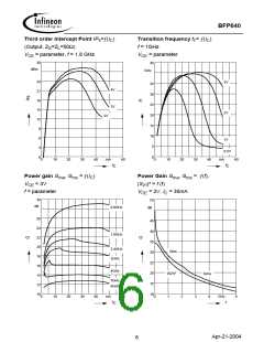
Transition frequency
30
40
-
GHz
f
T
I = 30 mA, V = 3 V, f = 1 GHz
C
CE
-
-
-
0.09
0.23
0.5
0.2 pF
Collector-base capacitance
= 3 V, f = 1 MHz
C
C
C
F
cb
ce
eb
V
CB
-
-
Collector emitter capacitance
= 3 V, f = 1 MHz
V
CE
Emitter-base capacitance
= 0.5 V, f = 1 MHz
V
EB
dB
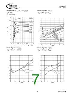
Noise figure
I = 5 mA, V = 3 V, f = 1.8 GHz, Z = Z
Sopt
-
-
0.65
1.3
-
-
C
CE
S
I = 5 mA, V = 3 V, f = 6 GHz, Z = Z
C
CE
S
Sopt
1)
Power gain, maximum stable
G
G
-
24
-
dB
dB
ms
ma
I = 30 mA, V = 3 V, Z = Z
,
,
C
CE
S
Sopt
Z = Z
, f = 1.8 GHz
L
Lopt
1)
-
12.5
-
Power gain, maximum available
I = 30 mA, V = 3 V, Z = Z
C
CE
S
Sopt
Z = Z
L
, f = 6 GHz
Lopt
2
Transducer gain
|S
|
dB
21e
I = 30 mA, V = 3 V, Z = Z = 50 Ω,
C
CE
S
L
f = 1.8 GHz
-
21
-
I = 30 mA, V = 3 V, Z = Z = 50 Ω,
C
CE
S
L
f = 6 GHz
-
-
10.5
26.5
-
-
2)
Third order intercept point at output
= 3 V, I = 30 mA, f = 1.8 GHz,
IP
dBm
3
V
CE
C
Z = Z = 50 Ω
S
L
1dB Compression point at output
P
-
13
-
-1dB
I = 30 mA, V = 3 V, Z = Z = 50 Ω,
C
CE
S
L
f = 1.8 GHz
1
1/2
G
= |S
/ S
| (k-(k²-1) ), G = |S
/ S
|
ma
21e
12e
ms
21e
12e
2
IP3 value depends on termination of all intermodulation frequency components.
Termination used for this measurement is 50Ω from 0.1 MHz to 6 GHz
Apr-21-2004
3

 INFINEON [ Infineon ]