ICS853P022
UAL LVCMOS / LVTTL-TO-DIFFERENTIAL
3.3V LVPECL TRANSLATOR
Integrated
Circuit
Systems, Inc.
D
3. Calculations and Equations.
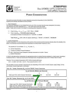
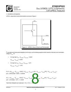
LVPECL output driver circuit and termination are shown in Figure 4.
VCC
Q1
VOUT
RL
50
VCC - 2V
Figure 4. LVPECL Driver Circuit and Termination
To calculate worst case power dissipation into the load, use the following equations which assume a 50Ω load, and a termination
voltage ofV - 2V.
CCO
•
•
For logic high, VOUT = V
= V
– 0.935V
OH_MAX
CCO_MAX
)
= 0.935V
OH_MAX
(V
- V
CC_MAX
For logic low, VOUT = V
= V
– 1.67V
CCO_MAX
OL_MAX
)
= 1.67V
OL_MAX
(V
- V
CCO_MAX
))
Pd_H = [(V
– (V
- 2V))/R ] * (V
- V
) = [(2V - (V
) = [(2V - (V
- V
/R ] * (V
- V
) =
OH_MAX
CCO_MAX
CCO_MAX
OH_MAX
_MAX
CCO
OH_MAX
CCO _MAX
OH_MAX
L
L
[(2V - 0.935V)/50Ω] * 0.935V = 19.92mW
))
Pd_L = [(V
– (V
- 2V))/R ] * (V
- V
- V
/R ] * (V
- V
) =
OL_MAX
CCO_MAX
CCO_MAX
OL_MAX
_MAX
OL_MAX
CCO_MAX
OL_MAX
L
CCO
L
[(2V - 1.67V)/50Ω] * 1.67V = 11.02mW
Total Power Dissipation per output pair = Pd_H + Pd_L = 30.94mW
853P022AG
www.icst.com/products/hiperclocks.html
REV. A FEBRUARY 23, 2005
8

 IDT [ INTEGRATED DEVICE TECHNOLOGY ]