Si4430/31/32-B1
3.2.1. SHUTDOWN State
The SHUTDOWN state is the lowest current consumption state of the device with nominally less than 15 nA of
current consumption. The shutdown state may be entered by driving the SDN pin (Pin 20) high. The SDN pin
should be held low in all states except the SHUTDOWN state. In the SHUTDOWN state, the contents of the
registers are lost and there is no SPI access.
When the chip is connected to the power supply, a POR will be initiated after the falling edge of SDN.
3.2.2. IDLE State
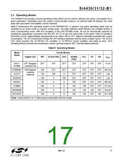
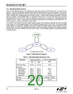
There are five different modes in the IDLE state which may be selected by "Register 07h. Operating Mode and
Function Control 1". All modes have a tradeoff between current consumption and response time to TX/RX mode.
This tradeoff is shown in Table 11. After the POR event, SWRESET, or exiting from the SHUTDOWN state the chip
will default to the IDLE-READY mode. After a POR event the interrupt registers must be read to properly enter the
SLEEP, SENSOR, or STANDBY mode and to control the 32 kHz clock correctly.
3.2.2.1. STANDBY Mode
STANDBY mode has the lowest current consumption of the five IDLE states with only the LPLDO enabled to
maintain the register values. In this mode the registers can be accessed in both read and write mode. The
STANDBY mode can be entered by writing 0h to "Register 07h. Operating Mode and Function Control 1". If an
interrupt has occurred (i.e., the nIRQ pin = 0) the interrupt registers must be read to achieve the minimum current
consumption. Additionally, the ADC should not be selected as an input to the GPIO in this mode as it will cause
excess current consumption.
3.2.2.2. SLEEP Mode
In SLEEP mode the LPLDO is enabled along with the Wake-Up-Timer, which can be used to accurately wake-up
the radio at specified intervals. See "8.6. Wake-Up Timer and 32 kHz Clock Source" on page 56 for more
information on the Wake-Up-Timer. SLEEP mode is entered by setting enwt = 1 (40h) in "Register 07h. Operating
Mode and Function Control 1". If an interrupt has occurred (i.e., the nIRQ pin = 0) the interrupt registers must be
read to achieve the minimum current consumption. Also, the ADC should not be selected as an input to the GPIO
in this mode as it will cause excess current consumption.
3.2.2.3. SENSOR Mode
In SENSOR mode either the Low Battery Detector, Temperature Sensor, or both may be enabled in addition to the
LPLDO and Wake-Up-Timer. The Low Battery Detector can be enabled by setting enlbd = 1 in "Register 07h.
Operating Mode and Function Control 1". See "8.4. Temperature Sensor" on page 53 and "8.5. Low Battery
Detector" on page 55 for more information on these features. If an interrupt has occurred (i.e., the nIRQ pin = 0)
the interrupt registers must be read to achieve the minimum current consumption.
3.2.2.4. READY Mode
READY Mode is designed to give a fast transition time to TX mode with reasonable current consumption. In this
mode the Crystal oscillator remains enabled reducing the time required to switch to TX or RX mode by eliminating
the crystal start-up time. READY mode is entered by setting xton = 1 in "Register 07h. Operating Mode and
Function Control 1". To achieve the lowest current consumption state the crystal oscillator buffer should be
disabled in “Register 62h. Crystal Oscillator Control and Test.” To exit READY mode, bufovr (bit 1) of this register
must be set back to 0.
3.2.2.5. TUNE Mode
In TUNE mode the PLL remains enabled in addition to the other blocks enabled in the IDLE modes. This will give
the fastest response to TX mode as the PLL will remain locked but it results in the highest current consumption.
This mode of operation is designed for frequency hopping spread spectrum systems (FHSS). TUNE mode is
entered by setting pllon = 1 in "Register 07h. Operating Mode and Function Control 1". It is not necessary to set
xton to 1 for this mode, the internal state machine automatically enables the crystal oscillator.
Rev 1.0
21

 IBM [ IBM ]