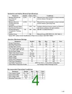
Insulation and Safety Related Specifications
Parameter
Symbol Value Units
Conditions
Minimum External Air
Gap (External
Clearance)
Minimum External
Tracking (External
Creepage)
Minimum Internal Plastic
Gap (Internal Clearance)
L(101)
7.1
mm
mm
mm
Measured from input terminals to output terminals,
shortest distance through air.
L(102)
7.4
Measured from input terminals to output terminals,
shortest distance path along body.
0.08
200
Insulation thickness between emitter and detector;
also known as distance through insulation.
Tracking Resistance
(Comparative Tracking
Index)
CTI
Volts DIN IEC 112/VDE 0303 Part 1
Isolation Group
IIIa
Material Group (DIN VDE 0110, 1/89, Table 1)
Option 300 - surface mount classification is Class A in accordance with CECC 00802.
Absolute Maximum Ratings
Parameter
Storage Temperature
Operating Temperature
Average Input Current
Symbol
TS
TA
IF(AVG)
Min.
-55.
-40
Max.
125
100
25
Units
°C
°C
Note
mA
1
Peak Transient Input Current
(<1 µs pulse width, 300 pps)
Reverse Input Voltage
“High” Peak Output Current
“Low” Peak Output Current
Supply Voltage
IF(TRAN)
VR
IOH(PEAK)
IOL(PEAK)
(VCC - VEE)
VO
1.0
5
2.5
2.5
35
VCC
250
295
A
Volts
A
2
2
A
0
0
Volts
Volts
mW
mW
Output Voltage
Output Power Dissipation
Total Power Dissipation
Lead Solder Temperature
Solder Reflow Temperature Profile
PO
PT
3
4
260°C for 10 sec., 1.6 mm below seating plane
See Package Outline Drawings section
Recommended Operating Conditions
Parameter
Symbol
(VCC - VEE)
IF(ON)
VF(OFF)
TA
Min.
15
7
-3.0
-40
Max.
30
16
0.8
100
Units
Volts
mA
V
Power Supply Voltage
Input Current (ON)
Input Voltage (OFF)
Operating Temperature
°C
1-185

 HP [ HEWLETT-PACKARD ]