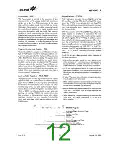
HT46R01A
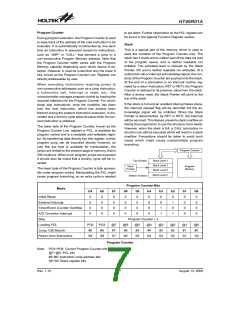
begin execution if the external interrupt is enabled and
the stack is not full. The external interrupt active edge
transition type, whether high to low, low to high or both
is specified in the CTRL1 register.
Arithmetic and Logic Unit - ALU
The arithmetic-logic unit or ALU is a critical area of the
microcontroller that carries out arithmetic and logic op-
erations of the instruction set. Connected to the main
microcontroller data bus, the ALU receives related in-
struction codes and performs the required arithmetic or
logical operations after which the result will be placed in
the specified register. As these ALU calculation or oper-
ations may result in carry, borrow or other status
changes, the status register will be correspondingly up-
dated to reflect these changes. The ALU supports the
following functions:
·
·
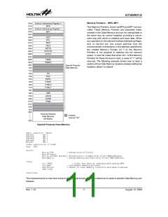
Location 008H
This internal vector is used by the Timer/Event Coun-
ter. If a counter overflow occurs, the program will jump
to this location and begin execution if the timer/event
counter interrupt is enabled and the stack is not full.
Location 00CH
This internal vector is used by the A/D converter.
When an A/D conversion cycle is complete, the pro-
gram will jump to this location and begin execution if
the A/D interrupt is enabled and the stack is not full.
·
·
·
Arithmetic operations: ADD, ADDM, ADC, ADCM,
SUB, SUBM, SBC, SBCM, DAA
0
0
0
0
0
0
0
4
8
H
H
H
Logic operations: AND, OR, XOR, ANDM, ORM,
XORM, CPL, CPLA
I
n
i
t
i
a
l
i
s
a
t
i
o
n
V
e
c
t
o
r
Rotation RRA, RR, RRCA, RRC, RLA, RL, RLCA,
RLC
E
x
t
e
r
n
a
l
I
n
t
e
r
r
u
p
t
V
e
c
t
o
r
·
·
Increment and Decrement INCA, INC, DECA, DEC
T
i
m
e
r
/
E
v
e
n
t
C
o
u
n
t
e
r
I
n
t
e
r
r
u
p
t
V
e
c
t
o
r
Branch decision, JMP, SZ, SZA, SNZ, SIZ, SDZ,
SIZA, SDZA, CALL, RET, RETI
0
0
C
H
A
/
D
C
o
n
v
e
r
t
e
t
r
I
n
t
e
r
r
u
p
t
V
e
c
o
r
0
1
0
H
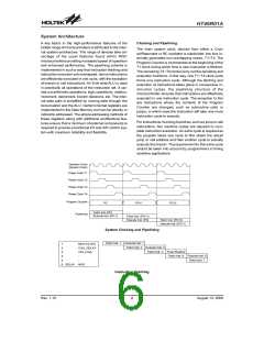
Program Memory
The Program Memory is the location where the user
code or program is stored. These devices are supplied
with One-Time Programmable, OTP, memory where us-
ers can program their application code into the device.
By using the appropriate programming tools, OTP de-
vices offer users the flexibility to freely develop their ap-
plications which may be useful during debug or for
products requiring frequent upgrades or program
changes. OTP devices are also applicable for use in ap-
plications that require low or medium volume production
runs.
0
1
4
H
3
0
0
H
3
F
F
H
1
4
b
i
t
s
Program Memory Structure
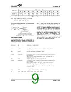
Look-up Table
Any location within the Program Memory can be defined
as a look-up table where programmers can store fixed
data. To use the look-up table, the table pointer must
first be setup by placing the lower order address of the
look up data to be retrieved in the table pointer register,
TBLP. This register defines the lower 8-bit address of
the look-up table.
Structure
The Program Memory has a capacity of 1K by 14. The
Program Memory is addressed by the Program Counter
and also contains data, table information and interrupt
entries. Table data, which can be setup in any location
within the Program Memory, is addressed by separate
table pointer registers.
After setting up the table pointer, the table data can be
retrieved from the current Program Memory page or last
Program Memory page using the ²TABRDC[m]² or
²TABRDL [m]² instructions, respectively. When these in-
structions are executed, the lower order table byte from
the Program Memory will be transferred to the user de-
fined Data Memory register [m] as specified in the in-
struction. The higher order table data byte from the
Program Memory will be transferred to the TBLH special
register. Any unused bits in this transferred higher order
byte will be read as ²0².
Special Vectors
Within the Program Memory, certain locations are re-
served for special usage such as reset and interrupts.
·
Location 000H
This vector is reserved for use by the device reset for
program initialisation. After a device reset is initiated, the
program will jump to this location and begin execution.
·
Location 004H
This vector is used by the external interrupt. If the ex-
ternal interrupt pin on the device receives an edge
transition, the program will jump to this location and
Rev. 1.10
8
August 13, 2008

 HOLTIC [ HOLT INTEGRATED CIRCUITS ]