HI-6110 (BUS MONITOR MODE)
MT OPERATION
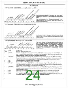
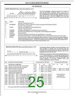
ERROR REGISTER (Read only) Read Address: 0111
The RT Error Register is cleared at reset and on receipt of a
valid MIL-STD-1553 Command Word. If an error is
encountered during message execution, the ERROR pin goes
high, the ERROR bit is set in the Status Register, and one or
more bits are set in the Error Register. The host may
interrogate the Error register at any time to determine the type
of error encountered.
Not used
0
0
0
0
0
0
0
0
MSB 15 14 13 12 11 10
9
8
7
6
5
4
3
2
1
0
LSB
BIT
NAME
-
FUNCTION
Not used. These bits are set to "0".
15- 10
9
8
7
6
5
4
3
2
1
0
RTPARERR
-
RTParity Error:There is a parity error in the pin-programmed RTaddress of this RT.
Not used. This bit is set to "0".
FFERR
-
Data was not available in theTransmit Data FIFO.
Not used. This bit is set to "0".
CONERR
GAPERR
WCERR
SYNCERR
MANERR
NORCV
Contiguous Message Error:Transmission was not contiguous.
Bus activity was detected in the 4.0 uS gap after a valid message was completed.
Word Count Error.
Sync Error: Expected Command Sync and got Data Sync, or vice versa.
Manchester Encoding Error:The decoder detected an error in Manchester encoding, bit count or parity.
This bit is set when a data word is expected while processing a receive command, but a gap is detected.
It is also set when an RT-to-RT "No Response Timeout" occurs, as defined per MIL-HDBK-1553, Figure 8
"RT-RT Timeout Measurement". The HI-6110 asserts this error when the bus dead-time between the RT-
RTcommand pair and the transmit RTStatus Word exceeds 15 uS.
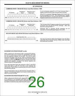
MESSAGE REGISTER (Read only) Read Address: 0110
The Message Register identifies command type when a new
valid command is received from the MIL-STD-1553 bus
controller. When a valid command is received, message type
is decoded and appropriate Message Register bit(s) are set.
Register bits 5 and 13 are mirrored.
Not Used
Message Type Flags
11 10
9
9
8
8
7
7
6
6
5
5
4
4
3
3
2
2
1
1
0
0
Broadcast commands occur when Command Word bits 15:11
= 11111. Values other than 11111 indicate the Remote Terminal
address for a non-broadcast command. Message Register bit
10 is set for any mode code or transmit command. This
enables detection of the three undefined mode code
command types listed under Bit 10 below.
0
0
13 12
MSB 15 14 13 12 11 10
LSB
Hex Last Valid Command Decoded
Command Word 1 Bit Fields
Command Word 2 Bit Fields
NON-MODE COMMANDS
15:11
RTA
11111
RTA
10
0
9:5
4:0
15:11 10
9:5
4:0
0001 Receive command from BC, not broadcast
0080 Receive command from BC, broadcast
0004 RT-RTcommand, not broadcast
0100 RT-RTcommand, broadcast
0402 Transmit command, RTto BC
MODE CODE COMMANDS
00001 -11110 XXXXX
0
00001 -11110 XXXXX
0
00001 -11110 XXXXX XXXXX
1
00001-11110 XXXXX
11111
RTA
0
00001 -11110 XXXXX not RTA 1 00001-11110 XXXXX
00001 -11110 XXXXX
1
0410 MC0 - MC15 T/R=1 no mode data, not broadcast RTA
0400 * MC0 - MC15 T/R=1 no mode data, broadcast 11111
0410 MC0 - MC15 T/R=0 not broadcast, UNDEFINED RTA
1
1
0
0
1
1
0
0
0000 or 11111 0XXXX
0000 or 11111 0XXXX
0000 or 11111 0XXXX
0000 or 11111 0XXXX
0000 or 11111 1XXXX
0000 or 11111 1XXXX
0000 or 11111 1XXXX
0000 or 11111 1XXXX
Command Word 2
only applies for
RT-RTcommands
0400 MC0 - MC15 T/R=0 broadcast , UNDEFINED
2420 MC16 - MC31 T/R=1 mode data, not broadcast
0400 * MC16 - MC31 T/R=1 broadcast , UNDEFINED
0040 MC16 - MC31 T/R=0 mode Data, not broadcast
0800 MC16 - MC31 T/R=0 mode data, broadcast
11111
RTA
11111
RTA
11111
*Two cases where 0400 is reset 550nS after RCV
HOLT INTEGRATED CIRCUITS
25

 HOLTIC [ HOLT INTEGRATED CIRCUITS ]