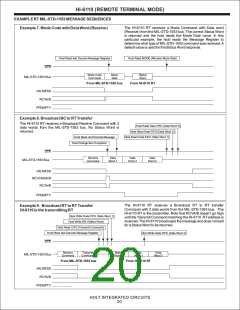
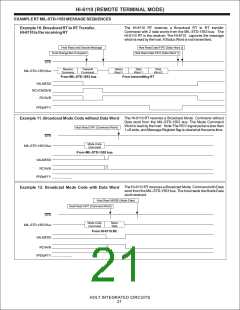
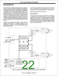
HI-6110 (BUS MONITOR MODE)
MT OPERATION
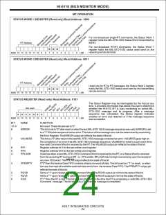
STATUS WORD 1 REGISTER (Read only) Read Address: 1000
For non-broadcast single-RT commands, the Status Word 1
register holds the MIL-STD-1553 Status Word transmitted by
the RT.
RT Address
For non-broadcast RT-RT commands, the Status Word 1
register holds the MIL-STD-1553 status word send by the
receiving remote terminal.
R
R
R
MSB 15 14 13 12 11 10
9
8
7
6
5
4
3
2
1
0
LSB
STATUS WORD 2 REGISTER (Read only) Read Address: 0011
RT Address
Used only for RT to RT messages, the Status Word 2 register
holds the MIL-STD-1553 status word sent by the transmitting
remote terminal.
R
R
R
MSB 15 14 13 12 11 10
9
8
7
6
5
4
3
2
1
0
LSB
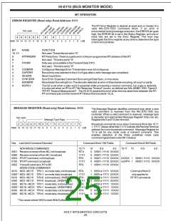
STATUS REGISTER (Read only) Read Address: 0101
The Status Register may be interrogated by the host at any
time. It provides information that allows the user to determine
whether the HI-6110 MT is busy monitoring an active MIL-
STD-1553 message and its progress. After a message
sequence has completed, the Status register indicates
whether an error was detected or if the message sequence
was successful.
Not used
0
0
0
0
0
0
0
MSB 15 14 13 12 11 10
9
8
7
6
5
4
3
2
1
0
LSB
BIT
15- 9
8
NAME
-
FUNCTION
Not used. These bits are set to "0".
ERROR
This bit is set to "0" after reset or when the last MIL-STD-1553 message sequence was valid. ERROR is set
to a "1" if the last sequence had an error. The nature of the message error can be determined by examining
the Error Register. The ERROR output pin reflects the state of this bit.
7
VALMESS
This bit is a "0" after reset or the last MIL-STD-1553 message contained an error. VALMESS goes high on
the completion of an error-free MIL-STD-1553 message sequence. VALMESS is reset to a zero each time
new valid Command Word is received by the RT. The VALMESS output pin reflects the state of this bit.
6
5
4
RF1
Register address bit 1 for the last written word register.
RF0
Register address bit 0 for the last written word register.
RFLAGN
Goes low when a new MIL-STD-1553 Command Word is received by the RT, or a Status Word is received
from the receiving RTduring an RT- to - RTtransfer. RFLAGN returns high momentarily upon the receipt of
any new 1553 word. The RFLAG output reflects the state of this bit.
3
FFEMPTY
If "0" then the receive Data FIFO contains at least one word of data. This bit is set to a "1" on reset, or when
the user has read all available received data words from the receiver Data FIFO. The FFEMPTYoutput pin
reflects the state of this bit.
2
1
0
RCVB
RCVA
IDLE
Set to a "1" upon receipt of a valid Command Word. The RCVB output pin mirrors the state of this bit.
Set to a "1" upon receipt of a valid Command Word. The RCVAoutput pin mirrors the state of this bit.
If "1" then the RT is idle. This bit is a zero throughout the time the RT is processing a valid MIL-STD-1553
Command. message. The bit returns to a "1" when the message is completed.
HOLT INTEGRATED CIRCUITS
24

 HOLTIC [ HOLT INTEGRATED CIRCUITS ]