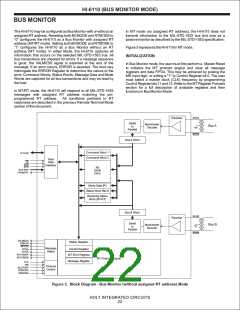
HI-6110 (BUS MONITOR MODE)
BUS MONITOR
The HI-6110 may be configured as Bus Monitor with or without an
assigned RT address. Resetting both BCMODE and RTMODE to
“0” configures the HI-6110 as a Bus Monitor with assigned RT
address (MT/RT mode). Setting both BCMODE and RTMODE to
“1” configures the HI-6110 as a Bus Monitor without an RT
address (MT mode). In either Mode, the HI-6110 captures all
information that occurs on the selected MIL-STD-1553 bus. All
bus transactions are checked for errors. If a message sequence
is good, the VALMESS signal is asserted at the end of the
message. If an error occurs, ERROR is asserted. The host may
interrogate the ERROR Register to determine the nature of the
error. Command Words, Status Words, Message Data and Mode
Words are captured for all bus transactions and may be read by
the host.
In MT mode (no assigned RT address), the HI-6110 does not
transmit information to the MIL-STD-1553 bus and acts as a
passive monitor as described by the MIL-STD-1553 specification.
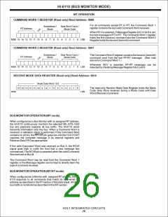
Figure 3 represents the HI-6110 in MTmode.
INITIALIZATION
In Bus Monitor mode, the user must first perform a Master Reset
to initialize the MT protocol engine and clear all message
registers and data FIFOs. This may be achieved by pulsing the
MR input high, or writing a "1" to Control Register bit 0. The user
must select a master clock (CLK) frequency by programming
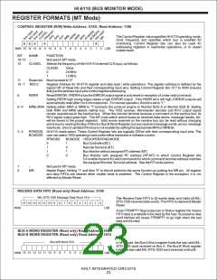
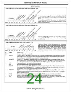
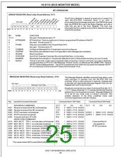
Control Register bits 11 and 12. Refer to the MT Register Formats
section for a full description of available registers and their
functions in Bus Monitor Mode.
In MT/RT mode, the HI-6110 will respond to all MIL-STD-1553
messages with assigned RT address matching the pin-
programmed RT address. All conditions pertinent to RT
responses are described in the previous Remote Terminal Mode
section of this document.
BUSA
Receiver
Serial
to
Parallel
Manchester
Decoder
Bus A
BUSA
Bus A Word
Command Word 1
Command Word 2
D15-D0
Host
Data
Interface
CS
R/W
STR
RA3-RA0
FFEMPTY
RX
DATA
FIFO
Mode Data (R)
Status Word Rec'd
Receiving Status
Word (RT-RT)
Bus B Word
BUSB
BUSB
Receiver
Serial
to
Parallel
Bus B
Manchester
Decoder
VALMESS
ERROR
RFLAG
RCVA
RCVB
RCVCMDA
RCVCMDB
Status Register
Message
Status
Control Register
MT Error Register
MT Protocol Engine
Message Register
CLK
MR
BCSTART
BCMODE
RTMODE
Protocol
Control
Figure 3. Block Diagram - Bus Monitor (without assigned RT address) Mode
HOLT INTEGRATED CIRCUITS
22

 HOLTIC [ HOLT INTEGRATED CIRCUITS ]