HT95LXXX
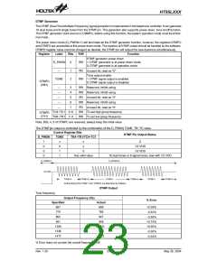
Line Control Function (Supported for HT95L400/40P, HT95L300/30P, HT95L200/20P, HT95L100/10P)
Register
Label
Bits
R/W
Function
6~0
RO
¾
Unused bit, read as ²0²
LINE
1: Enable the line control function
0: Disable the line control function
(22H)
LINEC
7
RW
The line control function is enabled by flag LINEC
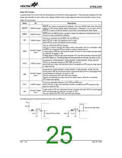
Conditions
Source to Enable
Line Control Function
LINEC
Operation Mode
1
Normal or Green mode
RTC time out interrupt
Port A wake-up
1
1
Sleep mode
Idle mode
RTC time out interrupt
Port A wake-up
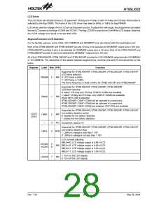
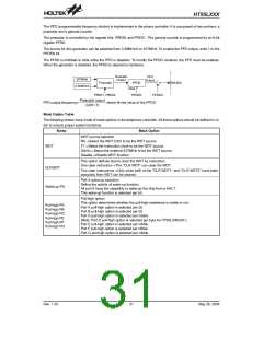
When the line control source is activated, the PO pin will be set to high signal. Clearing LINEC to 0 will terminate the line
control function and drive PO pin outputs low signal.
R
T
C
I
n
t
e
r
r
u
p
t
L
i
n
e
C
o
n
t
r
o
l
P
O
=
1
C
i
r
c
u
i
t
P
o
r
t
A
W
a
k
e
-
u
p
F
u
n
c
t
i
o
n
L
I
N
E
C
=
1
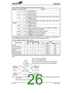
RTC Function
Register
Label
Bits
R/W
Function
6, 4~0 RO
¾
Unused bit, read as ²0²
1: Enable RTC function
0: Disable RTC function
RTCC
(24H)
RTCEN
RTCTO
5
7
RW
RW
1: RTC time-out occurs
0: RTC time-out not occurs
The real time clock (RTC) is used to supply a regular in-
ternal interrupt. Its time-out period is 1000ms. If the RTC
time-out occurs, the interrupt request flag RTCF and the
RTCTO flag will be set to 1. The interrupt vector for the
RTC is 14H. When the interrupt subroutine is serviced,
the interrupt request flag (RTCF) will be cleared to 0, but
the flag RTCTO remain in its original value. If the
RTCTO flag is not cleared, next RTC time-out interrupt
will occur.
V
D
E
T
1
.
1
5
V
R
e
f
e
r
e
n
c
e
V
o
l
t
a
g
e
R
1
L
B
F
G
L
B
I
N
R
2
L
B
E
N
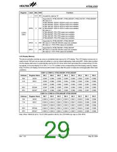
The battery low threshold is determined by external R1
and R2 resistors.
Low Battery Detection
VDETxR2
R1+ R2
1.15x(R1+ R2)
R2
(Supported for HT95L400/40P, HT95L300/30P,
HT95L200/20P, HT95L100/10P)
1.15=
® VDET=
The phone controller provides a circuit that detects the
LBIN pin voltage level. To enable this detection func-
tion, the LBEN should be written as 1. Once this function
is enabled, the detection circuit needs 50ms to be stable.
After that, the user could read the result from LBFG. The
low battery detect function will consume power. For
power saving, write 0 to LBEN if the low battery detec-
tion function is unnecessary.
If we want to detect VDET=2.4V
1.15x(R1+ R2)
then 2.4V=
® R1=1.087R2
R2
Rev. 1.20
27
May 26, 2004

 HOLTEK [ HOLTEK SEMICONDUCTOR INC ]