HT95LXXX
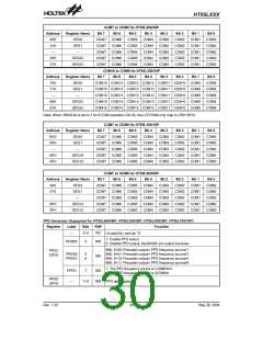
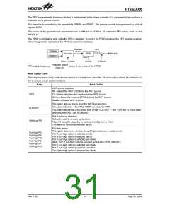
The PFD (programmable frequency divider) is implemented in the phone controller. It is composed of two portions: a
prescaler and a general counter.
The prescaler is controlled by the register bits, PRES0 and PRES1. The general counter is programmed by an 8-bit
register PFDD.
The source for this generator can be selected from 3.58MHz/4 or 32768Hz. To enable the PFD output, write 1 to the
PFDEN bit.
The PFDD is inhibited to write while the PFD is disabled. To modify the PFDD contents, the PFD must be enabled.
When the generator is disabled, the PFDD is cleared by hardware.
P
r
e
s
c
a
l
e
r
P
F
D
3
2
7
6
8
H
z
O
u
t
p
u
t
O
u
t
p
u
t
P
r
e
s
c
a
l
e
r
P
F
D
D
M
U
S
I
C
3
.
5
8
M
H
z
/
4
C
l
e
a
r
P
R
E
S
1
,
P
R
E
S
0
P
F
D
E
N
P
F
D
E
N
Prescaler output
2x(N+ 1)
PFD output frequency=
, where N=the value of the PFDD
Mask Option Table
The following shows many kinds of mask options in the telephone controller. All these options should be defined in or-
der to ensure proper system functions.
Name
Mask Option
WDT source selection
RC®Select the WDT OSC to be the WDT source.
T1®Select the instruction clock to be the WDT source.
32kHz®Select the external 32768Hz to be the WDT source.
Disable®Disable WDT function.
WDT
This option defines how to clear the WDT by instruction.
One clear instruction®The ²CLR WDT² can clear the WDT.
Two clear instructions®Only when both of the ²CLR WDT1² and ²CLR WDT2² have been
executed, then WDT can be cleared.
CLRWDT
Port A wake-up selection.
Define the activity of wake-up function.
All port A have the capability to wake-up the chip from a HALT.
This wake-up function is selected per bit.
Wake-up PA
Pull-high option.
This option determines whether the pull-high resistance is viable or not.
Port A pull-high option is selected per bit.
Pull-high PA
Pull-high PB
Pull-high PD
Pull-high PE
Pull-high PF
Pull-high PG
Port B pull-high option is selected per bit.
Port D pull-high option is selected per nibble.
(Note: Port D pull-high option is selected per byte for HT95L200/20P.)
Port E pull-high option is selected per nibble.
Port F pull-high option is selected per nibble.
Port G pull-high option is selected per nibble.
Rev. 1.20
31
May 26, 2004

 HOLTEK [ HOLTEK SEMICONDUCTOR INC ]