HT95LXXX
Phone controller also supports the dialer I/O flag to monitor the dialer status.
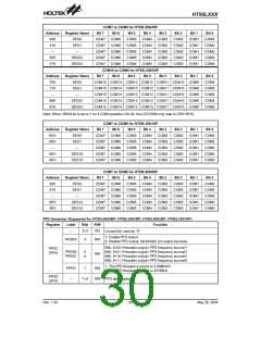
Register Label Bits R/W Function
1: The HFI pin level is 1.
0: The HFI pin level is 0.
HFI
0
1
RO
RO
1: The HFO pin level is 1.
0: The HFO pin level is 0.
HFO
Supported for HT95L400/40P, HT95L300/30P, HT95L200/20P, HT95L100/10P
HDI
2
3
RO 1: The HDI pin level is 1.
0: The HDI pin level is 0.
Supported for HT95L400/40P, HT95L300/30P, HT95L200/20P, HT95L100/10P
RO 1: The HDO pin level is 1.
HDO
DIALERIO
(16H)
0: The HDO pin level is 0.
1: The HKS pin level is 1.
RO
HKS
SPO
4
5
6
7
0: The HKS pin level is 0.
1: The PO pin is controlled by the combination of the HKS, HFI and HDI pin.
RW
0: The PO pin level is set to 0 by software.
1: The DNPO pin level is set to floating by software.
RW
SDNPO
XMUTE
0: The DNPO pin level is set to 0 by software.
1: The XMUTE pin is set to floating by software.
RW
0: The XMUTE pin is set to 0 by software.
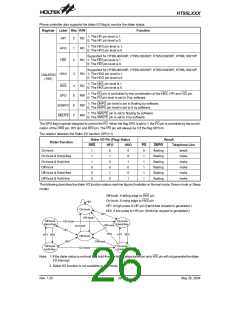
The SPO flag is special designed to control the PO. When the flag SPO is set to 1, the PO pin is controlled by the combi-
nation of the HKS pin, HFI pin and HDI pin. The PO pin will always be 0 if the flag SPO=0.
The relation between the Dialer I/O function (SPO=1)
Dialer I/O Pin (Flag) Status
Result
Telephone Line
Dialer Function
On-hook
HKS
HFO
HDO
PO
0
DNPO
floating
floating
floating
floating
floating
floating
1
1
1
0
0
0
0
1
0
0
1
0
0
0
1
0
0
1
break
make
make
make
make
make
On-hook & Hand-free
On-hook & Hold-line
Off-hook
1
1
1
Off-hook & Hand-free
Off-hook & Hold-line
1
1
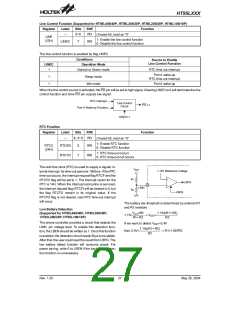
The following describes the dialer I/O function status machine figure (Available on Normal mode, Green mode or Sleep
mode):
Off-hook: A falling edge to HKS pin
On-hook: A rising edge to HKS pin
H
D
I
HFI: A high pulse to HFI pin (Hand-free request is generated.)
HDI: A low pulse to HDI pin (Hold-line request is generated.)
O
n
-
h
o
o
k
H
F
I
O
f
f
-
h
o
o
k
O
f
f
-
h
o
o
k
O
n
-
h
o
o
k
O
n
-
h
o
o
k
H
a
n
d
-
f
r
e
e
H
a
n
d
-
f
r
e
e
O
f
f
-
h
o
o
k
O
n
-
h
o
o
k
H
F
I
H
D
I
H
F
I
H
D
I
H
F
I
H
D
I
O
f
f
-
h
o
o
k
O
f
f
-
h
o
o
k
H
D
I
O
f
f
-
h
o
o
k
O
n
-
h
o
o
k
O
n
-
h
o
o
k
H
o
l
d
-
l
i
n
e
H
o
l
d
-
l
i
n
e
Note: 1. If the dialer status is on-hook and hold-line, the falling edge transition onto HDI pin will not generate the dialer
I/O interrupt.
2. Dialer I/O function is not available in Idle mode
Rev. 1.20
26
May 26, 2004

 HOLTEK [ HOLTEK SEMICONDUCTOR INC ]