HT48R063/064/065/066/0662/067
f
S
Y
S
[
[
[
[
P
P
P
P
W
W
W
W
M
M
M
M
]
]
]
]
=
=
=
=
1
1
1
1
0
0
0
0
0
1
2
3
P
P
P
P
W
W
W
W
M
M
M
M
5
5
5
0
1
1
/
/
/
1
1
1
2
2
2
8
8
8
5
5
5
5
0
0
1
1
/
/
/
/
1
1
1
1
2
2
2
2
8
8
8
8
5
5
5
5
0
1
1
2
/
/
/
/
1
1
1
1
2
2
2
2
8
8
8
8
5
2
/
1
2
8
P
W
M
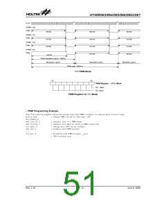
m
o
d
u
l
a
S
t
Y
i
S
o
n
p
e
r
i
o
d
:
1
2
8
/
f
M
o
d
u
l
a
t
i
o
n
c
y
c
l
e
0
M
o
d
u
l
a
t
i
o
n
c
y
c
l
e
M
o
1
d
u
l
a
t
i
o
P
W
M
c
y
S
c
Y
l
S
e
:
2
5
6
/
f
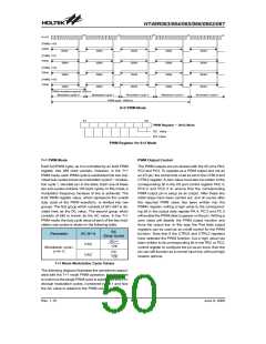
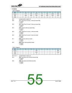
7+1 PWM Mode
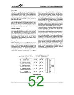
b
7
b
0
P
W
M
R
e
g
i
s
t
e
r
(
7
A
D
C
v
a
l
u
u
e
C
v
a
l
e
PWM Register for 7+1 Mode
·
PWM Programming Example
The following sample program shows how the PWM0 output is setup and controlled.
mov a,64h
mov pwm0,a
set ctrl0.5
set ctrl0.3
clr pac.4
set pa.4
: :
; setup PWM value of decimal 100
; select the 7+1 PWM mode
; select pin PA4 to have a PWM function
; setup pin PA4 as an output
; enable the PWM output
clr pa.4
; disable the PWM output _ pin
; PA4 forced low
Rev. 1.10
51
June 9, 2009

 HOLTEK [ HOLTEK SEMICONDUCTOR INC ]