HT48R063/064/065/066/0662/067
Timer/Event Counter will continue to record externally
changing logic events on the timer input TCn pin. As a
result when the timer overflows it will generate a timer
interrupt and corresponding wake-up source.
The residual value in the Timer/Event Counter, which
can now be read by the program, therefore represents
the length of the pulse received on the TCn pin. As the
enable bit has now been reset, any further transitions on
the external timer pin will be ignored. The timer cannot
begin further pulse width capture until the enable bit is
set high again by the program. In this way, single shot
pulse measurements can be easily made.
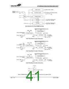
Pulse Width Capture Mode
In this mode, the Timer/Event Counter can be utilised to
measure the width of external pulses applied to the ex-
ternal timer pin. To operate in this mode, the Operating
Mode Select bit pair, TnM1/TnM0, in the Timer Control
Register must be set to the correct value as shown.
It should be noted that in this mode the Timer/Event
Counter is controlled by logical transitions on the external
timer pin and not by the logic level. When the Timer/Event
Counter is full and overflows, an interrupt signal is gener-
ated and the Timer/Event Counter will reload the value al-
ready loaded into the preload register and continue
counting. The interrupt can be disabled by ensuring that
the Timer/Event Counter Interrupt Enable bit in the corre-
sponding Interrupt Control Register, is reset to zero.
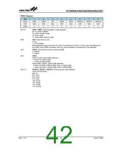
Control Register Operating Mode
Bit7 Bit6
Select Bits for the Pulse Width
1
1
Measurement Mode
In this mode the internal clock, fSYS , fSYS/4 or the LXT,
is used as the internal clock for the 8-bit Timer/Event
Counter. However, the clock source, fSYS, for the 8-bit
timer is further divided by a prescaler, the value of which
is determined by the Prescaler Rate Select bits
TnPSC2~TnPSC0, which are bits 2~0 in the Timer Con-
trol Register. After the other bits in the Timer Control
Register have been setup, the enable bit TnON, which is
bit 4 of the Timer Control Register, can be set high to en-
able the Timer/Event Counter, however it will not actu-
ally start counting until an active edge is received on the
external timer pin.
As the TCn pin is shared with an I/O pin, to ensure that
the pin is configured to operate as a pulse width capture
pin, two things have to happen. The first is to ensure that
the Operating Mode Select bits in the Timer Control
Register place the Timer/Event Counter in the pulse
width capture Mode, the second is to ensure that the
port control register configures the pin as an input.
Prescaler
Bits TnPSC0~TnPSC2 of the TMRnC register can be
used to define a division ratio for the internal clock
source of the Timer/Event Counter enabling longer time
out periods to be setup.
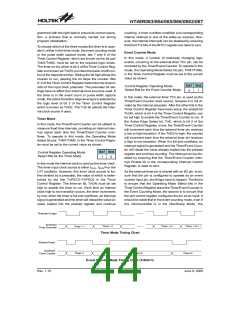
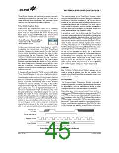
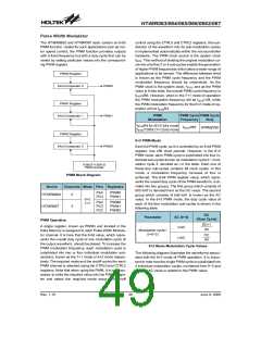
If the Active Edge Select bit TnEG, which is bit 3 of the
Timer Control Register, is low, once a high to low transi-
tion has been received on the external timer pin, the
Timer/Event Counter will start counting until the external
timer pin returns to its original high level. At this point the
enable bit will be automatically reset to zero and the
Timer/Event Counter will stop counting. If the Active
Edge Select bit is high, the Timer/Event Counter will be-
gin counting once a low to high transition has been re-
ceived on the external timer pin and stop counting when
the external timer pin returns to its original low level. As
before, the enable bit will be automatically reset to zero
and the Timer/Event Counter will stop counting. It is im-
portant to note that in the pulse width capture Mode, the
enable bit is automatically reset to zero when the exter-
nal control signal on the external timer pin returns to its
original level, whereas in the other two modes the en-
able bit can only be reset to zero under program control.
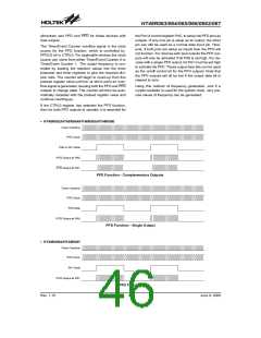
PFD Function
The Programmable Frequency Divider provides a
means of producing a variable frequency output suitable
for applications, such as piezo-buzzer driving or other
interfaces requiring a precise frequency generator.
Depending upon which device is used, there is either a
single output, PFD, or a complimentary output pair, PFD
and PFD. As the pins are shared with I/O pins, the func-
tion is selected using the CTRL0 register. Note that the
PFD pin is the inverse of the PDF pin generating a com-
plementary output and supplying more power to con-
nected interfaces such as buzzers. The PFDEN[1:0] in
CTRL0 register can select a single PFD pin or the com-
E
x
t
e
r
n
a
l
T
C
n
P
i
n
I
n
p
u
t
T
n
O
N
-
w
i
t
h
T
n
E
=
0
P
r
e
s
c
a
l
e
r
O
u
t
p
u
t
I
n
c
r
e
m
e
n
t
+
1
+
2
+
3
+
4
T
i
m
e
r
T
i
m
e
r
C
o
u
n
t
e
r
P
r
e
s
c
t
a
p
l
u
e
t
r
i
O
s
u
s
a
m
p
l
e
d
a
t
e
v
e
r
y
f
a
l
l
i
n
g
e
Pulse Width Measure Mode Timing Chart (TnEG=0)
Rev. 1.10
45
June 9, 2009

 HOLTEK [ HOLTEK SEMICONDUCTOR INC ]