HT48R063/064/065/066/0662/067
No matter what the source of the wake-up event is, once
a wake-up event occurs, there will be a time delay be-
fore normal program execution resumes. Consult the ta-
ble for the related time.
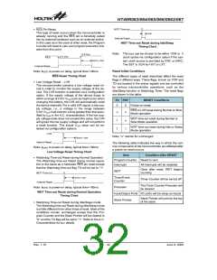
The Watchdog Timer clock can emanate from three dif-
ferent sources, selected by configuration option. These
are LXT, fSYS/4, or LIRC. It is important to note that when
the system enters the Idle/Sleep Mode the instruction
clock is stopped, therefore if the configuration options
have selected fSYS/4 as the Watchdog Timer clock
source, the Watchdog Timer will cease to function. For
systems that operate in noisy environments, using the
LIRC or the LXT as the clock source is therefore the rec-
ommended choice. The division ratio of the prescaler is
determined by bits 0, 1 and 2 of the WDTS register,
known as WS0, WS1 and WS2. If the Watchdog Timer in-
ternal clock source is selected and with the WS0, WS1
and WS2 bits of the WDTS register all set high, the
prescaler division ratio will be 1:128, which will give a
maximum time-out period.
Oscillator Type
Wake-up
Source
ERC, IRC
Crystal
External RES
PA Port
tRSDT + tSST1
tRSDT + tSST2
tSST1
tSST2
Interrupt
WDT Overflow
Note: 1. tSYS (system clock)
2. tRSTD is power-on delay, typical time=100ms
3. tSST1= 2 or 1024 tSYS
4. tSST2= 1024 tSYS
Under normal program operation, a Watchdog Timer
time-out will initialise a device reset and set the status bit
TO. However, if the system is in the Idle/Sleep Mode,
when a Watchdog Timer time-out occurs, the device will
be woken up, the TO bit in the status register will be set
and only the Program Counter and Stack Pointer will be
reset. Three methods can be adopted to clear the con-
tents of the Watchdog Timer. The first is an external
hardware reset, which means a low level on the external
reset pin, the second is using the Clear Watchdog Timer
software instructions and the third is when a HALT in-
struction is executed. There are two methods of using
software instructions to clear the Watchdog Timer, one
of which must be chosen by configuration option. The
first option is to use the single ²CLR WDT² instruction
while the second is to use the two commands ²CLR
WDT1² and ²CLR WDT2². For the first option, a simple
execution of ²CLR WDT² will clear the Watchdog Timer
while for the second option, both ²CLR WDT1² and
²CLR WDT2² must both be executed to successfully
clear the Watchdog Timer. Note that for this second op-
tion, if ²CLR WDT1² is used to clear the Watchdog
Timer, successive executions of this instruction will have
no effect, only the execution of a ²CLR WDT2² instruc-
tion will clear the Watchdog Timer. Similarly after the
²CLR WDT2² instruction has been executed, only a suc-
cessive ²CLR WDT1² instruction can clear the Watch-
dog Timer.
Wake-up Delay Time
Watchdog Timer
The Watchdog Timer, also known as the WDT, is pro-
vided to inhibit program malfunctions caused by the pro-
gram jumping to unknown locations due to certain
uncontrollable external events such as electrical noise.
Watchdog Timer Operation
It operates by providing a device reset when the Watch-
dog Timer counter overflows. Note that if the Watchdog
Timer function is not enabled, then any instructions re-
lated to the Watchdog Timer will result in no operation.
Setting up the various Watchdog Timer options are con-
trolled via the configuration options and two internal reg-
isters WDTS and CTRL1. Enabling the Watchdog Timer
can be controlled by both a configuration option and the
WDTEN bits in the CTRL1 internal register in the Data
Memory.
Configuration
Option
CTRL1
WDT
Register
Function
Disable
Disable
Enable
Disable
Enable
x
OFF
ON
ON
Watchdog Timer On/Off Control
The Watchdog Timer will be disabled if bits
WDTEN3~WDTEN0 in the CTRL1 register are written
with the binary value 1010B and WDT configuration op-
tion is disable. This will be the condition when the device
is powered up. Although any other data written to
WDTEN3~WDTEN0 will ensure that the Watchdog
Timer is enabled, for maximum protection it is recom-
mended that the value 0101B is written to these bits.
Rev. 1.10
29
June 9, 2009

 HOLTEK [ HOLTEK SEMICONDUCTOR INC ]