HT46R01B/02B/01N/02N
HT48R01B/02B/01N/02N
Program Counter Low Register - PCL
With the exception of the TO and PDF flags, bits in the
status register can be altered by instructions like most
other registers. Any data written into the status register
will not change the TO or PDF flag. In addition, opera-
tions related to the status register may give different re-
sults due to the different instruction operations. The TO
flag can be affected only by a system power-up, a WDT
time-out or by executing the ²CLR WDT² or ²HALT² in-
struction. The PDF flag is affected only by executing the
²HALT² or ²CLR WDT² instruction or during a system
power-up.
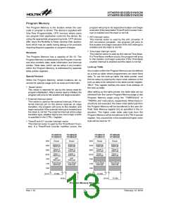
To provide additional program control functions, the low
byte of the Program Counter is made accessible to pro-
grammers by locating it within the Special Purpose area
of the Data Memory. By manipulating this register, direct
jumps to other program locations are easily imple-
mented. Loading a value directly into this PCL register
will cause a jump to the specified Program Memory lo-
cation, however, as the register is only 8-bit wide, only
jumps within the current Program Memory page are per-
mitted. When such operations are used, note that a
dummy cycle will be inserted.
The Z, OV, AC and C flags generally reflect the status of
the latest operations.
Status Register - STATUS
In addition, on entering an interrupt sequence or execut-
ing a subroutine call, the status register will not be
pushed onto the stack automatically. If the contents of
the status registers are important and if the interrupt rou-
tine can change the status register, precautions must be
taken to correctly save it. Note that bits 0~3 of the
STATUS register are both readable and writeable bits.
This 8-bit register contains the zero flag (Z), carry flag
(C), auxiliary carry flag (AC), overflow flag (OV), power
down flag (PDF), and watchdog time-out flag (TO).
These arithmetic/logical operation and system manage-
ment flags are used to record the status and operation of
the microcontroller.
·
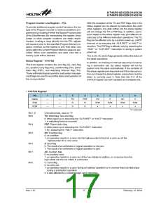
STATUS Register
Bit
Name
R/W
7
6
5
TO
R
4
PDF
R
3
OV
R/W
x
2
Z
1
AC
R/W
x
0
C
¾
¾
¾
¾
¾
¾
R/W
x
R/W
x
POR
0
0
²x² unknown
Bit 7, 6
Unimplemented, read as ²0²
TO: Watchdog Time-Out flag
Bit 5
Bit 4
Bit 3
0: After power up or executing the ²CLR WDT² or ²HALT² instruction
1: A watchdog time-out occurred.
PDF: Power down flag
0: After power up or executing the ²CLR WDT² instruction
1: By executing the ²HALT² instruction
OV: Overflow flag
0: no overflow
1: an operation results in a carry into the highest-order bit but not a carry out of the
highest-order bit or vice versa.
Bit 2
Bit 1
Z: Zero flag
0: The result of an arithmetic or logical operation is not zero
1: The result of an arithmetic or logical operation is zero
AC: Auxiliary flag
0: no auxiliary carry
1: an operation results in a carry out of the low nibbles in addition, or no borrow from the
high nibble into the low nibble in subtraction
Bit 0
C: Carry flag
0: no carry-out
1: an operation results in a carry during an addition operation or if a borrow does not take place
during a subtraction operation
C is also affected by a rotate through carry instruction.
Rev.1.10
17
February 12, 2010

 HOLTEK [ HOLTEK SEMICONDUCTOR INC ]