HT48R50A-1/HT48C50-1
Pin Assignment
P
P
P
P
P
P
P
P
B
B
A
A
A
A
B
B
5
4
3
2
1
0
3
2
1
2
3
4
5
6
7
8
9
1
1
1
1
1
1
1
1
1
1
2
2
2
2
2
4
4
4
4
4
4
4
4
4
3
3
3
3
3
3
3
3
3
3
2
2
2
2
2
8
7
6
5
4
3
2
1
0
9
8
7
6
5
4
3
2
1
0
9
8
7
6
5
P
B
B
A
A
A
A
6
7
4
5
6
7
P
P
P
P
P
N
C
C
C
C
N
P
P
B
B
1
0
/
/
B
B
Z
Z
N
0
1
2
3
4
5
6
7
8
9
0
1
2
3
4
N
P
B
B
A
A
A
A
6
7
4
5
6
7
P
B
5
1
2
3
4
5
6
7
8
9
1
1
1
1
1
2
2
2
2
2
2
2
2
2
1
1
1
1
1
8
7
6
5
4
3
2
1
0
9
8
7
6
5
N
N
N
N
C
C
C
C
O
S
S
C
C
2
1
/
/
P
P
G
G
2
1
P
P
B
4
O
P
P
A
3
V
R
T
P
P
P
P
P
P
P
P
P
D
D
S
P
P
A
2
E
P
P
A
1
P
D
7
M
R
1
P
P
A
0
P
D
6
D
D
D
D
C
C
C
C
C
3
2
1
0
7
6
5
4
3
O
S
S
C
C
2
1
/
/
P
P
G
G
2
1
P
P
B
B
3
2
P
P
D
D
5
4
O
V
D
D
P
P
B
B
1
0
/
/
B
B
Z
Z
V
S
S
R
E
S
0
1
2
3
4
P
G
0
/
I
N
T
P
C
5
/
T
M
R
1
V
S
S
T
M
R
0
P
P
P
C
C
C
4
3
2
P
G
0
/
I
N
T
P
C
0
P
C
0
/
T
M
R
C
0
P
P
C
C
1
2
P
1
H
T
4
8
R
5
0
A
-
1
/
H
T
4
8
C
5
0
-
1
-
A
H
T
4
8
R
5
0
A
-
1
/
H
T
4
8
C
5
0
-
1
-
A
2
8
S
K
D
I
P
-
A
/
S
O
P
-
A
4
8
S
S
O
P
-
A
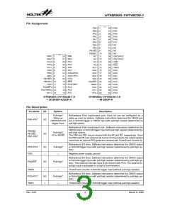
Pin Description
Pin Name
I/O
Options
Description
Pull-high*
Wake-up
Bidirectional 8-bit input/output port. Each bit can be configured as a
wake-up input by options. Software instructions determine the CMOS out-
PA0~PA7
I/O
CMOS/Schmitt put or Schmitt trigger or CMOS input with pull-high resistor (determined by
trigger Input
pull-high option).
Bidirectional 8-bit input/output port. Software instructions determine the
CMOS output or Schmitt trigger input with pull-high resistor (determined by
pull-high option).
PB0/BZ
PB1/BZ
PB2~PB7
Pull-high*
I/O
I/O or BZ/BZ
The PB0 and PB1 are pin-shared with the BZ and BZ, respectively. Once
the PB0 and PB1 are selected as buzzer driving outputs, the output signals
come from an internal PFD generator (shared with Timer/Event Counter 0).
Bidirectional I/O lines. Software instructions determine the CMOS output
or Schmitt trigger input with pull-high resistor (determined by pull-high op-
tion).
PD0~PD7
VSS
I/O
Pull-high*
Negative power supply, ground
¾
¾
Bidirectional I/O lines. Software instructions determine the CMOS output
or Schmitt trigger input with pull-high resistor (determined by pull-high op-
tion). This external interrupt input is pin-shared with PG0. The external in-
terrupt input is activated on a high to low transition.
PG0/INT
I/O
Pull-high*
TMR0
I
I/O
I
Timer/Event Counter 0 Schmitt trigger input (without pull-high resistor)
¾
Pull-high*
¾
Bidirectional I/O lines. Software instructions determine the CMOS output
or Schmitt trigger input with pull-high resistor (determined by pull-high op-
tion).
PC0~PC7
TMR1
Timer/Event Counter 1 Schmitt trigger input (without pull-high resistor)
Rev. 2.00
3
March 8, 2006

 HOLTEK [ HOLTEK SEMICONDUCTOR INC ]