HT48R05A-1/HT48C05/HT48R06A-1/HT48C06/HT48R08A-1
·
Table location
Program Memory - ROM
The program memory is used to store the program in-
structions which are to be executed. It also contains
data, table, and interrupt entries, and is organized into
512´14 bits (HT48R05A-1/HT48C05), 1024´14 bits
(HT48R06A-1/HT48C06) or 2048´14 bits
(HT48R08A-1), addressed by the program counter and
table pointer.
Any location in the program memory can be used as
look-up tables. The instructions ²TABRDC [m]² (the
current page, 1 page=256 words) and ²TABRDL [m]²
(the last page; However this statement is not valid for
the HT48R05A-1/HT48C05 devices) transfer the con-
tents of the lower-order byte to the specified data
memory, and the higher-order byte to TBLH (08H).
Only the destination of the lower-order byte in the ta-
ble is well-defined, the other bits of the table word are
transferred to the lower portion of TBLH, and the re-
maining 2 bits are read as ²0². The Table Higher-order
byte register (TBLH) is read only. The table pointer
(TBLP) is a read/write register (07H), which indicates
the table location. Before accessing the table, the lo-
cation must be placed in TBLP. The TBLH is read only
and cannot be restored. If the main routine and the
ISR (Interrupt Service Routine) both employ the table
read instruction, the contents of the TBLH in the main
routine are likely to be changed by the table read in-
struction used in the ISR. Errors can occur. In other
words, using the table read instruction in the main rou-
tine and the ISR simultaneously should be avoided.
However, if the table read instruction has to be applied
in both the main routine and the ISR, the interrupt is
supposed to be disabled prior to the table read in-
struction. It will not be enabled until the TBLH has
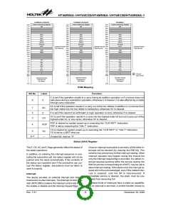
Certain locations in the program memory are reserved
for special usage:
·
Location 000H
This area is reserved for program initialization. After
chip reset, the program always begins execution at lo-
cation 000H.
·
Location 004H
This area is reserved for the external interrupt service
program. If the INT input pin is activated, the interrupt
is enabled and the stack is not full, the program begins
execution at location 004H.
·
Location 008H
This area is reserved for the timer/event counter inter-
rupt service program. If a timer interrupt results from a
timer/event counter overflow, and if the interrupt is en-
abled and the stack is not full, the program begins ex-
ecution at location 008H.
H
T
4
8
R
0
5
A
-
1
/
H
T
4
8
C
0
5
H
T
4
8
R
0
6
A
-
1
/
H
T
4
8
C
0
6
H
T
4
8
R
0
8
A
-
1
0
0
0
H
I
n
i
t
i
a
l
i
z
a
t
i
o
n
V
e
c
t
o
r
I
n
i
t
i
a
l
i
z
a
t
i
o
n
V
e
c
t
o
r
I
n
i
t
i
a
l
i
z
a
t
i
o
n
V
e
c
t
o
r
0
0
4
H
E
x
t
e
r
n
a
l
I
n
t
e
r
r
u
p
t
V
e
c
t
o
r
E
x
t
e
r
n
a
l
I
n
t
e
r
r
u
p
t
V
e
c
t
o
r
E
x
t
e
r
n
a
l
I
n
t
e
r
r
u
p
t
V
e
c
t
o
r
0
0
8
H
T
i
m
e
r
/
C
o
u
n
t
e
r
T
i
m
e
r
/
C
o
u
n
t
e
r
T
i
m
e
r
/
C
o
u
n
t
e
r
I
n
t
e
r
r
u
p
t
V
e
c
t
o
r
I
n
t
e
r
r
u
p
t
V
e
c
t
o
r
I
n
t
e
r
r
u
p
t
V
e
c
t
o
r
1
F
F
H
2
0
0
H
3
F
F
H
4
0
0
H
N
o
t
I
m
p
l
e
m
e
n
t
e
d
7
F
F
H
1
4
b
i
t
s
1
4
b
i
t
s
1
4
b
i
t
s
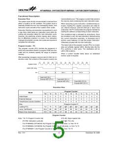
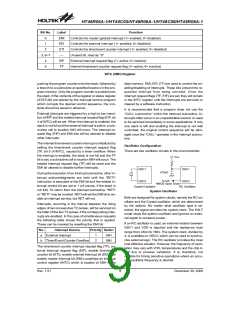
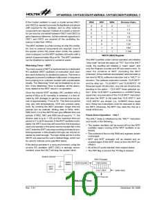
Program Memory
Table Location
*5
Instruction
*10
*9
*8
P8
1
*7
*6
*4
*3
*2
*1
*0
TABRDC [m]
TABRDL [m]
P10
1
P9
1
@7
@7
@6
@6
@5
@5
@4
@4
@3
@3
@2
@2
@1
@1
@0
@0
Table Location
P10~P8: Current program counter bits
Note: *10~*0: Table location bits
@7~@0: Table pointer bits
For HT48R05A-1/HT48C05, the table address location is 9 bits, i.e. from *8~*0
For HT48R06A-1/HT48C06, the table address location is 10 bits, i.e. from *9~*0
For HT48R08A-1, the table address location is 11 bits, i.e. from *10~*0
Rev. 1.51
6
December 30, 2008
图片预览")
 HOLTEK [ HOLTEK SEMICONDUCTOR INC ]