HT48R05A-1/HT48C05/HT48R06A-1/HT48C06/HT48R08A-1
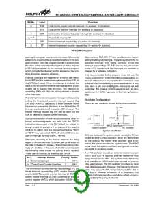
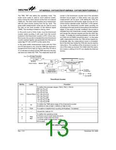
Bit No.
Label
EMI
EEI
ETI
¾
Function
Controls the master (global) interrupt (1= enabled; 0= disabled)
Controls the external interrupt (1= enabled; 0= disabled)
Controls the timer/event counter interrupt (1= enabled; 0= disabled)
Unused bit, read as ²0²
0
1
2
3, 6~7
4
5
EIF
TF
External interrupt request flag (1= active; 0= inactive)
Internal timer/event counter request flag (1= active; 0= inactive)
INTC (0BH) Register
pushing the program counter onto the stack, followed by
a branch to a subroutine at specified location in the pro-
gram memory. Only the program counter is pushed onto
the stack. If the contents of the register or status register
(STATUS) are altered by the interrupt service program
which corrupts the desired control sequence, the con-
tents should be saved in advance.
data memory. EMI, EEI, ETI are used to control the en-
abling/disabling of interrupts. These bits prevent the re-
quested interrupt from being serviced. Once the
interrupt request flags (TF, EIF) are set, they will remain
in the INTC register until the interrupts are serviced or
cleared by a software instruction.
It is recommended that a program does not use the
²CALL subroutine² within the interrupt subroutine. In-
terrupts often occur in an unpredictable manner or need
to be serviced immediately in some applications. If only
one stack is left and enabling the interrupt is not well
controlled, the original control sequence will be dam-
aged once the ²CALL² operates in the interrupt subrou-
tine.
External interrupts are triggered by a high to low transi-
tion of INT and the related interrupt request flag (EIF; bit
4 of INTC) will be set. When the interrupt is enabled, the
stack is not full and the external interrupt is active, a sub-
routine call to location 04H will occur. The interrupt re-
quest flag (EIF) and EMI bits will be cleared to disable
other interrupts.
The internal timer/event counter interrupt is initialized by
setting the timer/event counter interrupt request flag
(TF; bit 5 of INTC), caused by a timer overflow. When
the interrupt is enabled, the stack is not full and the TF
bit is set, a subroutine call to location 08H will occur. The
related interrupt request flag (TF) will be reset and the
EMI bit cleared to disable further interrupts.
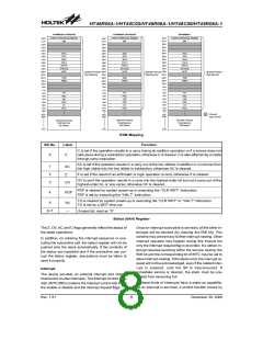
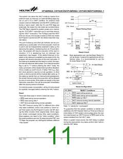
Oscillator Configuration
There are two oscillator circuits in the microcontroller.
V
D
D
O
S
C
1
O
S
C
1
4
7
0
p
F
During the execution of an interrupt subroutine, other in-
terrupt acknowledgments are held until the ²RETI²
instruction is executed or the EMI bit and the related in-
terrupt control bit are set to 1 (of course, if the stack is
not full). To return from the interrupt subroutine, ²RET²
or ²RETI² may be invoked. RETI will set the EMI bit to en-
able an interrupt service, but RET will not.
S
Y
S
O
S
C
2
O
S
C
2
N
M
O
S
O
p
e
n
D
r
a
i
n
C
r
y
s
t
a
l
O
s
c
i
l
l
a
t
o
r
R
C
O
s
c
i
l
l
a
t
o
r
System Oscillator
Both are designed for system clocks, namely the RC os-
cillator and the Crystal oscillator, which are determined
by the options. No matter what oscillator type is se-
lected, the signal provides the system clock. The HALT
mode stops the system oscillator and ignores an exter-
nal signal to conserve power.
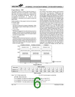
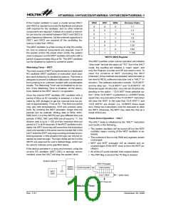
Interrupts, occurring in the interval between the rising
edges of two consecutive T2 pulses, will be serviced on
the latter of the two T2 pulses, if the corresponding inter-
rupts are enabled. In the case of simultaneous requests
the following table shows the priority that is applied.
These can be masked by resetting the EMI bit.
If an RC oscillator is used, an external resistor between
OSC1 and VDD is required and the resistance must
range from 24kW to 1MW. The system clock, divided by
4, is available on OSC2, which can be used to synchro-
nize external logic. The RC oscillator provides the most
cost effective solution. However, the frequency of oscil-
lation may vary with VDD, temperatures and the chip it-
self due to process variations. It is, therefore, not
suitable for timing sensitive operations where an accu-
rate oscillator frequency is desired.
No.
a
Interrupt Source
External Interrupt
Timer/Event Counter Overflow
Priority Vector
1
2
04H
08H
b
The timer/event counter interrupt request flag (TF), ex-
ternal interrupt request flag (EIF), enable timer/event
counter bit (ETI), enable external interrupt bit (EEI) and
enable master interrupt bit (EMI) constitute an interrupt
control register (INTC) which is located at 0BH in the
Rev. 1.51
9
December 30, 2008
图片预览")
 HOLTEK [ HOLTEK SEMICONDUCTOR INC ]