HT46R51/HT46R52
S
Y
S
[
P
W
M
]
=
1
0
0
P
W
M
2
5
/
6
4
2
2
2
2
5
5
6
6
/
/
/
/
6
6
6
6
4
4
4
4
2
2
2
2
5
5
5
6
/
/
/
/
6
6
6
6
4
4
4
4
2
2
2
2
5
5
5
5
/
/
/
/
6
6
6
6
4
4
4
4
2
2
2
2
5
6
6
6
/
/
/
/
6
6
6
6
4
4
4
4
[
P
W
M
]
=
1
0
1
P
W
M
2
2
2
6
6
6
/
/
/
6
6
6
4
4
4
[
P
W
M
]
=
1
0
2
P
W
M
[
P
W
M
]
=
1
0
3
P
W
M
P
W
M
m
o
d
u
l
a
t
i
o
n
p
e
r
i
o
d
:
6
4
/
f
M
o
d
u
l
a
t
i
o
n
c
y
c
l
e
0
M
o
d
u
l
a
t
i
o
n
c
y
c
l
e
1
M
o
d
u
l
a
t
i
o
n
c
y
c
l
e
2
M
o
d
u
l
a
t
i
o
n
c
y
c
l
e
3
M
o
d
u
l
a
t
i
o
n
c
y
c
l
e
0
P
W
M
c
y
c
l
e
:
2
5
6
/
f
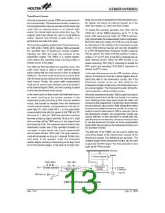
(6+2) PWM Mode
A/D Converter
and falling edge means that the A/D conversion has
started. In order to ensure that the A/D conversion is
completed, the START should remain at ²0² until the
EOCB is cleared to ²0² (end of A/D conversion). The bit
7 of the ACSR is used for testing purposes only. Bit 7 of
the ACSR register is used for test purposes only and
must not be used for other purposes by the application
program. Bit1 and bit0 of the ACSR register are used to
select the A/D clock source.
The 5 channels 12-bit resolution A/D converter are im-
plemented in this microcontroller.
The A/D converter contains 4 special registers which
are; ADRL (20H), ADRH (21H), ADCR (22H) and ACSR
(23H). The ADRH and ADRL are A/D result register
higher-order byte and lower-order byte and are
read-only. After the A/D conversion is completed, the
ADRH and ADRL should be read to get the conversion
result data. The ADCR is an A/D converter control regis-
ter, which defines the A/D channel number, analog
channel select, start A/D conversion control bit and the
end of A/D conversion flag. If the users want to start an
A/D conversion, define PB configuration, select the con-
verted analog channel, and give START bit a raising
edge and falling edge (0®1®0). At the end of A/D con-
version, the EOCB bit is cleared and an A/D converter
interrupt occurs (if the A/D converter interrupt is en-
abled). The ACSR is A/D clock setting register, which is
used to select the A/D clock source.
When the A/D conversion has completed, the A/D inter-
rupt request flag will be set. The EOCB bit is set to ²1²
when the START bit is set from ²0² to ²1².
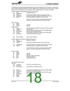
Important Note for A/D initialisation:
Special care must be taken to initialise the A/D con-
verter each time the Port B A/D channel selection bits
are modified, otherwise the EOCB flag may be in an un-
defined condition. An A/D initialisation is implemented
by setting the START bit high and then clearing it to zero
within 10 instruction cycles of the Port B channel selec-
tion bits being modified. Note that if the Port B channel
selection bits are all cleared to zero then an A/D initialis-
ation is not required.
The A/D converter control register is used to control the
A/D converter. The bit2~bit0 of the are used to select an
analog input channel. There are a total of five channels
to select. The bit5~bit3 of the ADCR are used to set PB
configurations. PB can be an analog input or as digital
I/O line determined by these 3 bits. Once a PB line is se-
lected as an analog input, the I/O functions and pull-high
resistor of this I/O line are disabled and the A/D con-
verter circuit is powered on. The EOCB bit (bit6 of the
ADCR) is end of A/D conversion flag. Check this bit to
know when the A/D conversion is completed.
Bit No. Label
Function
Selects the A/D converter clock source
00= system clock/2
0
1
ADCS0
ADCS1
01= system clock/8
10= system clock/32
11= undefined
2~6
7
¾
Unused bit, read as ²0²
TEST For test mode used only
The START bit of the ADCR is used to begin the conver-
sion of the A/D converter. Giving START bit a rising edge
ACSR (23H) Register
Rev. 1.40
16
July 12, 2005

 HOLTEK [ HOLTEK SEMICONDUCTOR INC ]