HT45R37
f
S
Y
S
f
S
S
o
u
r
c
e
f
S
C
o
n
f
i
g
u
r
a
t
T
i
o
i
m
n
e
O
B
p
a
t
i
s
o
e
n
I
n
t
e
r
3
2
7
6
8
C
H
o
z
n
f
i
g
u
r
a
t
i
o
n
1
d
2
1
5
1
2
1
5
S
2 / f
D
i
v
i
~
e
2
b
y
2
2
/
S
~
f
O
p
t
i
o
n
3
2
K
_
I
N
T
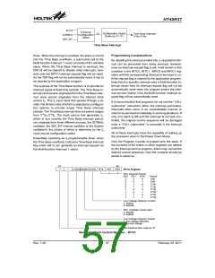
Time Base Interrupt
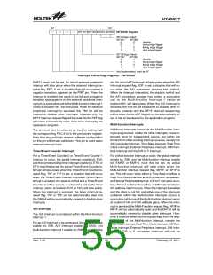
Programming Considerations
flows. When the interrupt is enabled, the stack is not full
and the Time Base overflows, a subroutine call to the
Multi-function Interrupt 1 vector at location18H, will take
place. When the Time Base Interrupt is serviced, the
EMI bit will be cleared to disable other interrupts, how-
ever only the MF1F interrupt request flag will be reset.
As the TBF flag will not be automatically reset, it has to
be cleared by the application program.
By disabling the interrupt enable bits, a requested inter-
rupt can be prevented from being serviced, however,
once an interrupt request flag is set, it will remain in this
condition in the INTC0, INTC1, MFIC0 and MFIC1 reg-
isters until the corresponding interrupt is serviced or un-
til the request flag is cleared by the application program.
Note that if a specific interrupt uses a Multi-function In-
terrupt vector then its interrupt request flag will not be
automatically reset when the program enters the inter-
rupt service routine. Only the Multi-function interrupt re-
quest flag will be automatically reset.
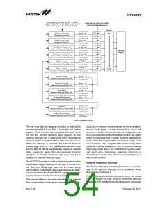
The purpose of the Time Base function is to provide an
interrupt signal at fixed time periods. The Time Base in-
terrupt clock source originates from the Time Base inter-
rupt clock source originates from the internal clock
source fS. This fS input clock first passes through a di-
vider, the division ratio of which is selected by configura-
tion options to provide longer Time Base interrupt
periods. The Time Base interrupt time-out period ranges
from 212/fS~215/fS. The clock source that generates fS,
which in turn controls the Time Base interrupt period,
can originate from three different sources, the 32768Hz
oscillator, the 32K_INT internal oscillator or the System
oscillator/4, the choice of which is determine by the fS
clock source configuration option.
It is recommended that programs do not use the ²CALL
subroutine² instruction within the interrupt subroutine.
Interrupts often occur in an unpredictable manner or
need to be serviced immediately in some applications. If
only one stack is left and the interrupt is not well con-
trolled, the original control sequence will be damaged
once a ²CALL subroutine² is executed in the interrupt
subroutine.
All of these interrupts have the capability of waking up
the processor when in the Power Down Mode.
Essentially operating as a programmable timer, when
the Time Base overflows it will set a Time Base interrupt
flag which will in turn generate an Interrupt request via
the Multi-function Interrupt 1 vector.
Only the Program Counter is pushed onto the stack. If
the contents of the status or other registers are altered
by the interrupt service program, which may corrupt the
desired control sequence, then the contents should be
saved in advance.
b
7
b
0
L
V
D
Q
O
O
S
C
L
R
V
T
D
2
C
R
T
1
R
T
0
C
R
T
C
R
e
g
i
s
t
e
r
R
R
T
T
C
2
I
n
t
e
r
r
u
p
t
P
e
r
i
o
R
T
1
R
T
0
P
e
r
i
o
d
8
9
1
1
1
1
1
1
0
0
0
0
1
1
1
1
0
0
1
1
0
0
1
1
0
1
0
1
0
1
0
1
2
2
2
2
2
2
2
2
/
S
S
f
/
f
0
1
2
3
4
5
/
/
/
/
/
/
S
S
S
S
S
S
f
f
f
f
f
f
L
1
0
o
:
:
w
V
o
l
t
a
g
e
D
e
t
e
c
t
o
e
d
n
i
a
b
l
e
s
s
a
a
b
b
l
e
R
1
0
T
C
O
s
c
i
l
l
a
t
o
r
Q
u
i
c
:
:
l
d
e
e
i
n
a
r
b
l
e
L
1
0
o
:
:
w
V
o
l
t
a
g
e
D
e
t
e
c
t
o
l
n
o
w
v
o
l
t
a
g
e
d
e
t
e
c
o
m
a
l
v
o
l
t
a
g
e
N
o
t
i
m
p
l
e
s
m
e
"
n
0
t
"
e
d
,
r
e
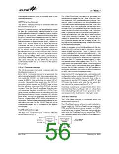
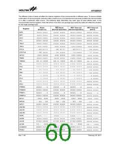
Real Time Clock Control Register - RTCC
Rev. 1.20
57
February 25, 2011
图片预览")
 HOLTEK [ HOLTEK SEMICONDUCTOR INC ]