HT45R37
automatically reset and must be manually reset by the
application program.
For a Real Time Clock interrupt to be generated, the
global interrupt enable bit, EMI , Real Time Clock inter-
rupt enable bit, ERTI, and Multi-function Interrupt 1 en-
able bit, EMF1I, must first be set. An actual Real Time
Clock interrupt will take place when the Real Time Clock
request flag, RTF, is set, a situation that will occur when
the Real Time Clock overflows. When the interrupt is en-
abled, the stack is not full and the Real Time Clock over-
flows, a subroutine call to the Multi-function Interrupt 1
vector at location18H, will take place. When the Real
Time Clock interrupt is serviced, the EMI bit will be
cleared to disable other interrupts, however only the
MF1F interrupt request flag will be reset. As the RTF
flag will not be automatically reset, it has to be cleared
by the application program.
SPI/I2C Interface Interrupt
The SPI/I2C interface Interrupt is contained within the
Multi-function Interrupt 0.
For an /I2C interrupt to occur, the global interrupt enable
bit, EMI, the corresponding interrupt enable bit, ESIM
and Multi-function Interrupt 0 enable bit, EMF0I, must be
first set. An actual SPI/I2C interrupt will take place when
the SPI/I2C reset function interface request flag, SIMF, is
set, a situation that will occur when a byte of data has
been transmitted or received by the SPI/I2C interface or
when an I2C address match occurs. When the interrupt
is enabled, the stack is not full and a byte of data has
been transmitted or received by the SPI/I2C interface or
an I2C address match occurs, a subroutine call to the
Multi-function Interrupt 0 vector at location 14H, will take
place. When the interrupt is serviced, the Multi-function
Interrupt 0 request flag, MF0F, will be automatically re-
set and the EMI bit will be automatically cleared to dis-
able other interrupts. As the SIMF flag will not be
automatically reset it has to be cleared by the applica-
tion program.
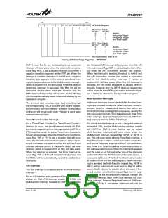
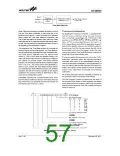
Similar in operation to the Time Base interrupt, the pur-
pose of the RTC interrupt is also to provide an interrupt
signal at fixed time periods. The RTC interrupt clock
source originates from the internal clock source fS. This
fS input clock first passes through a divider, the division
ratio of which is selected by programming the appropri-
ate bits in the RTCC register to obtain longer RTC inter-
rupt periods whose value ranges from 28/fS~215/fS. The
clock source that generates fS, which in turn controls the
RTC interrupt period, can originate from three different
sources, the 32768Hz oscillator, 32K_INT oscillator or
the System oscillator/4, the choice of which is determine
by the fS clock source configuration option.
C/R to F Converter Interrupt
The C/R to converter Interrupt is contained within the
Multi-function Interrupt 0.
For a C/R to F converter interrupt to be generated, the
global interrupt enable bit, EMI, the corresponding inter-
rupt enable bit, ERCOCI and Multi-function Interrupt 0
enable bit, EMF0I, must be first set. An actual C/R to F
converter interrupt will take place when the C/R to F
converter interrupt request flag, RCOCF, is set, a situa-
tion that will occur when one of the C/R to F converter
counters, Timer A or Timer B, overflows. When the inter-
rupt is enabled, the stack is not full and a C/R to F con-
verter counter overflow occurs, a subroutine call to the
Multi-function Interrupt 0 vector at location 14H, will take
place. When the interrupt is serviced, the Multi-function
Interrupt 0 request flag, MF0F, will be automatically re-
set and the EMI bit will be automatically cleared to dis-
able other interrupts. As the RCOCF flag will not be
automatically reset it has to be cleared by the applica-
tion program.
Note that the RTC interrupt period is controlled by both
configuration options and an internal register RTCC. A
configuration option selects the source clock for the in-
ternal clock fS, and the RTCC register bits RT2, RT1 and
RT0 select the division ratio. Note that the actual divi-
sion ratio can be programmed from 28 to 215.
Essentially operating as a programmable timer, when
the Real Time Clock overflows it will set a Real Time
Clock interrupt flag which will in turn generate an Inter-
rupt request via the Multi-function Interrupt 1 vector.
Time Base Interrupt
The Time Base Interrupt is contained within the
Multi-function Interrupt 1.
For a Time Base Interrupt to be generated, the global in-
terrupt enable bit, EMI,Time Base Interrupt enable bit,
ETBI, and Multi-function Interrupt enable 1 bit, EMF1I,
must first be set. An actual Time Base Interrupt will take
place when the Time Base Interrupt request flag, TBF, is
set, a situation that will occur when the Time Base over-
Real Time Clock Interrupt
The Real Time Clock Interrupt is contained within the
Multi-function Interrupt 1.
f
S
Y
S
8
1
5
f
S
S
o
u
r
c
e
D
i
v
i
d
~
e
2
b
y
2
f
S
R
T
C
I
n
t
e
r
r
u
p
t
3
2
7
6
8
C
H
o
z
n
f
i
g
u
r
a
S
t
i
e
o
t
n
b
y
R
T
C
C
1
2
1
5
S
2 / f
2
/
S
~
f
O
p
t
i
o
n
R
e
g
i
s
t
e
r
3
2
K
_
I
N
T
R
1
T
0
R
2
T
R
T
RTC Interrupt
Rev. 1.20
56
February 25, 2011
图片预览")
 HOLTEK [ HOLTEK SEMICONDUCTOR INC ]