HT45R37
b
7
b
0
I
N
T
I
1
N
S
T
1
1
S
0
I
N
T
I
0
N
S
T
1
E
I
D
N
G
T
E
0
S
R
0
e
g
i
s
t
e
r
I
I
N
N
T
T
0
0
E
d
g
e
S
e
l
e
c
t
S
1
I
N
T
0
S
0
0
0
1
1
0
1
0
1
d
r
f
d
i
u
s
a
b
l
e
i
s
i
l
n
i
g
e
d
g
e
t
a
l
n
g
e
d
g
e
a
l
e
d
g
e
t
r
I
I
N
N
T
T
1
1
E
D
g
e
S
e
l
e
c
t
S
1
I
N
T
1
S
0
0
0
1
1
0
1
0
1
d
r
f
d
i
u
s
a
b
l
e
i
s
i
l
n
i
g
g
g
e
e
d
r
g
e
t
a
l
n
g
e
d
g
e
a
l
e
d
g
e
t
r
N
o
t
i
m
p
l
e
m
e
n
t
e
d
,
r
e
a
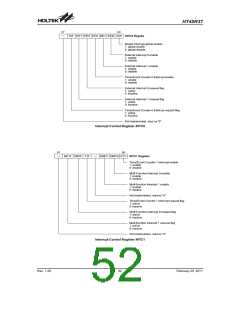
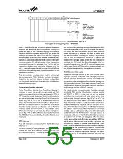
Interrupt Active Edge Register - INTEDGE
EMF1I, must first be set. An actual external peripheral
interrupt will take place when the external interrupt re-
quest flag, PEF, is set, a situation that will occur when a
negative transition, appears on the PINT pin. When the
interrupt is enabled, the stack is not full and a negative
transition type appears on the external peripheral inter-
rupt pin, a subroutine call to the Multi-function Interrupt 1
vector at location18H, will take place. When the external
peripheral interrupt is serviced, the EMI bit will be
cleared to disable other interrupts, however only the
MF1F interrupt request flag will be reset. As the PEF flag
will not be automatically reset, it has to be cleared by the
application program.
set. An actual A/D Interrupt will take place when the A/D
Interrupt request flag, ADF, is set, a situation that will oc-
cur when the A/D conversion process has finished.
When the interrupt is enabled, the stack is not full and
the A/D conversion process has ended, a subroutine
call to the Multi-function Interrupt 1 vector at
location18H, will take place. When the A/D Interrupt is
serviced, the EMI bit will be cleared to disable other in-
terrupts, however only the MF1F interrupt request flag
will be reset. As the ADF flag will not be automatically re-
set, it has to be cleared by the application program.
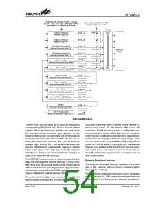
Multi-function Interrupts
Additional interrupts known as the Multi-function inter-
rupts are provided. Unlike the other interrupts, these in-
terrupts have no independent source, but rather are
formed from other existing interrupt sources, namely the
A/D Converter interrupt, Time Base interrupt, Real Time
Clock interrupt, External Peripheral interrupt, SIM Inter-
face Interrupt and the C/R to F interrupt.
The pin must also be setup as an input by setting high
the corresponding PDC.6 bit in the port control register.
Note that any pull-high resistor software configuration
on this pin will remain valid even if the pin is used as an
external interrupt input.
Timer/Event Counter Interrupt
For a Timer/Event Counter 0 or Timer/Event Counter 1
interrupt to occur, the global interrupt enable bit, EMI,
and the corresponding timer interrupt enable bit, ET0I or
ET1I must first be set. An actual Timer/Event Counter in-
terrupt will take place when the Timer/Event Counter re-
quest flag, T0F or T1F is set, a situation that will occur
when the Timer/Event Counter overflows. When the in-
terrupt is enabled, the stack is not full and a Timer/Event
Counter overflow occurs, a subroutine call to the timer
interrupt vector at location 0CH or 10C, will take place.
When the interrupt is serviced, the timer interrupt re-
quest flag, T0F or T1F, will be automatically reset and
the EMI bit will be automatically cleared to disable other
interrupts.
For a Multi-function interrupt to occur, the global interrupt
enable bit, EMI, and the Multi-function interrupt enable
bit, EMF0I or EMF1I, must first be set. An actual
Multi-function interrupt will take place when the
Multi-function interrupt request flag, MF0F, or MF1F is
set. This will occur when either a Time Base overflow, a
Real Time Clock overflow, an A/D conversion completion,
an External Peripheral Interrupt, C/R to F converter coun-
ters, Timer A or Timer B overflow or SIM data transfer or
I2C address match occurs. When the interrupt is enabled
and the stack is not full, and either one of the interrupts
contained within the Multi-function interrupts occurs, a
subroutine call to one of the Multi-function interrupt vector
at location 014H or 018H will take place. When the inter-
rupt is serviced, the Multi-Function request flag, MF0F or
MF1F, will be automatically reset and the EMI bit will be
automatically cleared to disable other interrupts. How-
ever, it must be noted that the request flags from the origi-
nal source of the Multi-function interrupt, namely the
Time-Base interrupt, Real Time Clock interrupt, A/D Con-
verter interrupt, External Peripheral interrupt, SIM Inter-
face or C/R to F converter Interrupt will not be
A/D Interrupt
The A/D Interrupt is contained within the Multi-function
Interrupt 1.
For an A/D Interrupt to be generated, the global interrupt
enable bit, EMI, A/D Interrupt enable bit, EADI, and
Multi-function Interrupt 1 enable bit, EMF1I, must first be
Rev. 1.20
55
February 25, 2011
图片预览")
 HOLTEK [ HOLTEK SEMICONDUCTOR INC ]