HT36A1
0
0
0
0
0
0
0
8
H
H
other type is for wavetable code, which is addressed by
the start address ST11~0. On the program type,
WA15~0= PF2~0 ´ 213+ PC12~0. On the wave table
ROM type, WA15~0=ST11~0 ´ 25.
D
e
v
i
c
e
i
n
i
t
i
a
l
i
z
a
t
i
o
n
p
r
o
g
r
a
m
T
i
m
e
r
C
o
u
n
t
e
r
0
i
n
t
e
r
r
u
p
t
s
u
b
r
o
u
t
i
n
e
0
0
0
C
H
T
i
m
e
r
C
o
u
n
t
e
r
1
i
n
t
e
r
r
u
p
t
s
u
b
r
o
u
t
i
n
e
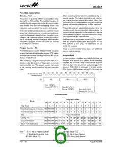
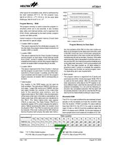
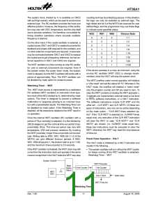
Program Memory - ROM
P
r
o
g
r
a
m
n
0
0
H
R
O
M
The program memory is used to store the program in-
structions which are to be executed. It also contains
data, table, and interrupt entries, and is organized into
8192´16 bits, addressed by the bank pointer, program
counter and table pointer.
L
o
o
k
-
u
p
t
a
b
l
e
(
2
5
6
w
o
r
d
s
)
n
F
F
H
L
o
o
k
-
u
p
t
a
b
l
e
(
2
5
6
w
o
r
d
s
)
1
F
F
F
H
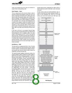
Certain locations in the program memory of each bank
are reserved for special usage:
1
6
b
i
t
s
N
o
t
e
:
n
r
a
n
g
e
s
f
r
o
m
0
0
t
o
1
F
.
·
Location 000H on bank0
Program Memory for Each Bank
This area is reserved for the initialization program. Af-
ter chip reset, the program always begins execution at
location 000H on bank0.
tion, the contents of the TBLH in the main routine are
likely to be changed by the table read instruction used
in the ISR. Errors can occur. In this case, using the ta-
ble read instruction in the main routine and the ISR si-
multaneously should be avoided. However, if the table
read instruction has to be applied in both the main rou-
tine and the ISR, the interrupt should be disabled prior
to the table read instruction. It will not be enabled until
the TBLH has been backed up. All table related in-
structions need 2 cycles to complete the operation.
These areas may function as normal program mem-
ory depending upon user requirements.
·
Location 008H
This area is reserved for the Timer Counter 0 interrupt
service program on each bank. If timer interrupt results
from a timer counter 0 overflow, and if the interrupt is
enabled and the stack is not full, the program begins ex-
ecution at location 008H corresponding to its bank.
·
Location 00CH
This area is reserved for the Timer Counter 1 interrupt
service program on each bank. If a timer interrupt re-
sults from a Timer Counter 1 overflow, and if the inter-
rupt is enabled and the stack is not full, the program
begins execution at location 00CH corresponding to
its bank.
·
Bank pointer
The program memory is organized into 8 banks and
each bank into 8192´16 bits of program ROM. PF2~0
is used as the bank pointer. After an instruction has
been executed to write data to the PF register to se-
lect a different bank, note that the new bank will not be
selected immediately. It is not until the following in-
struction has completed execution that the bank will
be actually selected. It should be note that the PF reg-
ister has to be cleared before setting to output mode.
·
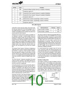
Table location
Any location in the ROM space can be used as
look-up tables. The instructions TABRDC [m] (the cur-
rent page, 1 page=256 words) and TABRDL [m] (the
last page) transfer the contents of the lower-order
byte to the specified data memory, and the
higher-order byte to TBLH (08H). Only the destination
of the lower-order byte in the table is well-defined, the
higher-order byte of the table word are transferred to
the TBLH. The Table Higher-order byte register
(TBLH) is read only. The Table Pointer (TBLP) is a
read/write register (07H), which indicates the table lo-
cation. Before accessing the table, the location must
be placed in TBLP. The TBLH is read only and cannot
be restored. If the main routine and the ISR (Interrupt
Service Routine) both employ the table read instruc-
Wavetable ROM
The ST11~0 is used to defined the start address of each
sample on the wavetable and read the waveform data
from the location. HT36A1 provides 16 output address
lines from WA15~0, the ST11~0 is used to locate the
major 16 bits i.e. WA15~5 and the undefined data from
WA4~0 is always set to 00000b. So the start address of
each sample have to be located at a multiple of 32. Oth-
Table Location
Instruction(s)
*15 *14 *13 *12 *11 *10
*9
*8
P8 @7 @6 @5 @4 @3 @2 @1 @0
@7 @6 @5 @4 @3 @2 @1 @0
*7
*6
*5
*4
*3
*2
*1
*0
TABRDC [m] P15 P14 P13 P12 P11 P10 P9
TABRDL [m] P15 P14 P13
1
1
1
1
1
Table Location
Note: *12~*0: Bits of table location
P12~P8: Bits of current Program Counter
@7~@0: Bits of table pointer
P15~P13: Bits of bank PF2~PF0
Rev. 1.00
7
August 15, 2005

 HOLTEK [ HOLTEK SEMICONDUCTOR INC ]