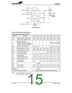
HT36A1
The system clock, divided by 4, is available on OSC2
with pull-high resistor, which can be used to synchronize
external logic. The RC oscillator provides the most cost
effective solution. However, the frequency of the oscilla-
tion may vary with VDD, temperature, and the chip itself
due to process variations. It is therefore, not suitable for
timing sensitive operations where accurate oscillator
frequency is desired.
counting and lose its protecting purpose. In this situation
the logic can only be restarted by external logic. The
high nibble and bit 3 of the WDTS are reserved for user
defined flags, and the programmer may use these flags
to indicate some specified status.
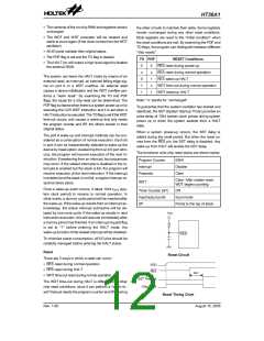
WS2
WS1
WS0
Division Ratio
0
0
0
0
1
1
1
1
0
0
1
1
0
0
1
1
0
1
0
1
0
1
0
1
1:1
1:2
On the other hand, if the crystal oscillator is selected, a
crystal across OSC1 and OSC2 is needed to provide the
feedback and phase shift required for the oscillator, and
no other external components are required. A resonator
may be connected between OSC1 and OSC2 to replace
the crystal and to get a frequency reference, but two ex-
ternal capacitors in OSC1 and OSC2 are required.
1:4
1:8
1:16
1:32
1:64
1:128
The WDT oscillator is a free running on-chip RC oscilla-
tor, and no external components are required. Even if
the system enters the power down mode, the system
clock is stopped, but the WDT oscillator still works with a
period of approximately 78ms. The WDT oscillator can
be disabled by mask option to conserve power.
If the device operates in a noisy environment, using the
on-chip RC oscillator (WDT OSC) is strongly recom-
mended, since the HALT will stop the system clock.
The WDT overflow under normal operation will initialize
a ²chip reset² and set the status bit TO. Whereas in the
HALT mode, the overflow will initialize a ²warm reset²
only the program counter and SP are reset to zero. To
clear the WDT contents (including the WDT prescaler ),
3 methods are implemented; external reset (a low level
to RES), software instructions, or a HALT instruction.
The software instructions include CLR WDT and the
other set - CLR WDT1 and CLR WDT2. Of these two
types of instructions, only one can be active depending
on the mask option - ²CLR WDT times selection op-
tion². If the ²CLR WDT² is selected (i.e. CLRWDT times
equal one), any execution of the CLR WDT instruction
will clear the WDT. In case ²CLR WDT1² and ²CLR
WDT2² are chosen (i.e. CLRWDT times equal two),
these two instructions must be executed to clear the
WDT; otherwise, the WDT may reset the chip because
of time-out.
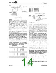
Watchdog Timer - WDT
The WDT clock source is implemented by a dedicated
RC oscillator (WDT oscillator) or instruction clock (sys-
tem clock of the MCU divided by 4), determined by mask
options. This timer is designed to prevent a software
malfunction or sequence jumping to an unknown loca-
tion with unpredictable results. The Watchdog Timer can
be disabled by mask option. If the Watchdog Timer is
disabled, all the executions related to the WDT result in
no operation.
Once the internal WDT oscillator (RC oscillator with a
period of 78ms normally) is selected, it is first divided by
256 (8-stages) to get the nominal time-out period of ap-
proximately 20ms. This time-out period may vary with
temperature, VDD and process variations. By invoking
the WDT prescaler, longer time-out periods can be real-
ized. Writing data to WS2, WS1, WS0 (bit 2,1,0 of the
WDTS) can give different time-out periods. If WS2,
WS1, WS0 all equal to 1, the division ratio is up to 1:128,
and the maximum time-out period is 2.6 seconds.
Power Down Operation - HALT
The HALT mode is initialized by a HALT instruction and
results in the following...
If the WDT oscillator is disabled, the WDT clock may still
come from the instruction clock and operate in the same
manner except that in the HALT state the WDT may stop
·
The system oscillator will turn off but the WDT oscilla-
tor keeps running (If the WDT oscillator is selected).
Watchdog Timer - WDT
S
y
s
t
e
m
C
l
o
c
k
/
8
W
D
T
P
r
e
s
c
a
l
e
r
M
a
s
k
8
-
b
i
t
C
o
u
n
t
e
r
7
-
b
i
t
C
o
u
n
t
e
r
O
p
t
i
o
n
S
e
l
e
c
t
W
D
T
O
S
C
8
-
t
o
-
1
M
U
X
W
S
0
~
W
S
2
W
D
T
T
i
m
e
-
o
u
t
Watchdog Timer
Rev. 1.00
11
August 15, 2005

 HOLTEK [ HOLTEK SEMICONDUCTOR INC ]